Chery Tiggo 5 (T21). Service manual — part 276
25–
37
25
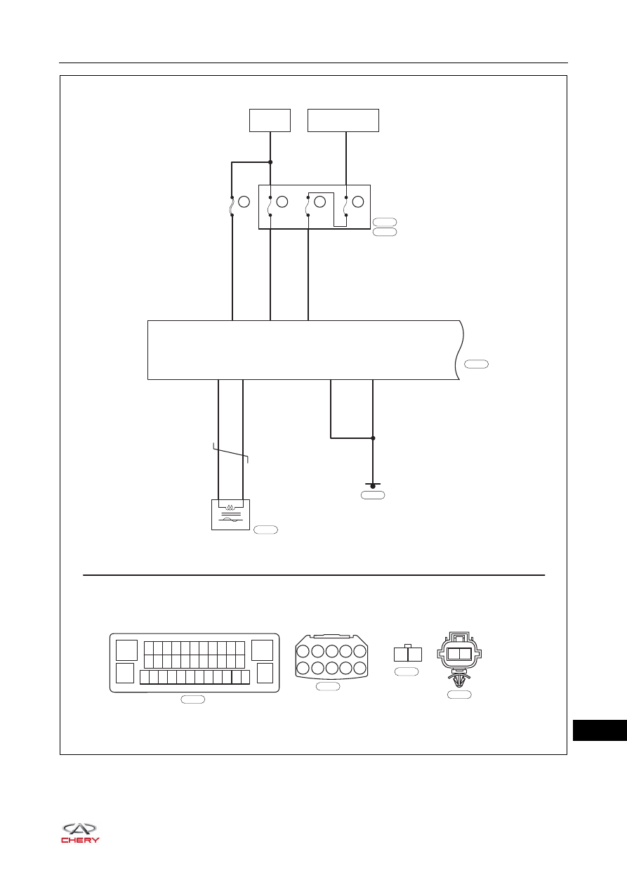
ET21250070
BATTERY
ABS
CONTROL
MODULE
IGNITION SWITCH
ON OR START
EF47
25A
I1
A10
1
25
28
MF01
40A
EF34
20A
EF36
10A
ENGINE
COMPARTMENT
FUSE AND
RELAY BOX
R
RL
R
13
12 11 10 9 8 7 6 5 4 3 2
24 23 22 21 20 19 18 17 16 15 14
37 36 35 34 33 32 31 30 29 28 27 26
1
38
25
Gr
E-074
Gr
E-076
A1
A2
A3
A4
A5
A6
A7
A8 A9 A10
I2
I1
E-074
E-076
B
E-085
E-085
38
13
Br
B
E-042
16
4
1
2
FRONT RIGHT
WHEEL SPEED
SENSOR
GY
WY
B
E-036
1
2
E-036
25–
38
25
Diagnosis Procedure
a. Turn ignition switch to LOCK.
b. Disconnect the negative battery cable.
c. Disconnect the front right wheel speed sensor connector E-036.
d. Check if the wire harnesses are worn, pierced, pinched or partially broken.
e. Look for broken, bent, protruded or corroded terminals.
f. Check if related connector pins are in good condition.
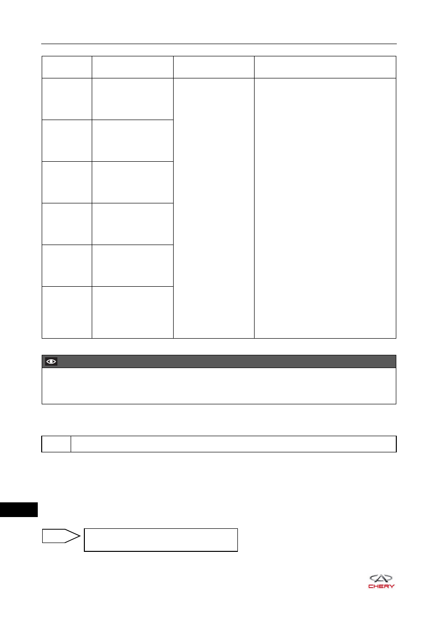
DTC Code
DTC Definitions
DTC Detection
Conditions
Possible Cause
C0034-00
Right Front Wheel
Speed Sensor
These DTCs occur
when any of the
following conditions is
met:
1. ABS control module
assembly detects
that the wheel
speed sensor signal
wire is short to
ground.
2. Wheel speed sensor
line is open.
3. ABS control module
assembly detects
that the wheel
speed sensor signal
wire is short to
power supply.
4. ABS control module
assembly detects
that the wheel
speed sensor power
supply wire is short
to ground.
5. Wheel speed sensor
signal is invalid.
Wheel speed sensor signal wire is
connecting with the power supply wire
in reverse.
Wheel speed sensor signal wire is
short to ground.
Wheel speed sensor line is open,
connector is loose or broken.
Wheel speed sensor signal wire is
short to power supply.
Wheel speed sensor power supply
wire is short to ground.
Sensor head or plug pin is damaged.
Wheel speed sensor is interfered by
magnetic field outside (wheel or axle is
not demagnetized).
Wheel speed sensor body is
malfunctioning.
Ring gear is not installed, has teeth
missing, dirty, demagnetized or off
center.
Clearance between sensor and ring
gear is excessive.
Number of ring gear teeth is wrong.
Tire size is not as specified.
ABS control module assembly is
damaged.
C0034-09
Right Front Wheel
Speed Sensor
C0034-11
Right Front Wheel
Speed Sensor
C0034-12
Right Front Wheel
Speed Sensor
C0034-13
Right Front Wheel
Speed Sensor
C0034-29
Right Front Wheel
Speed Sensor
CAUTION
When performing electrical equipment diagnosis and test, always refer to the circuit diagram for related
circuit and component information.
1
Check front right wheel speed sensor wire harness and connector
Repair or replace front right wheel speed
sensor wire harness and connector
NG
25–
39
25
a. Turn ignition switch to LOCK.
b. Disconnect the negative battery cable.
c. Check front right wheel speed sensor mounting bolt for looseness.
d. Check if excessive clearance exists between the installation position of front right wheel speed sensor and
front steering knuckle.
e. Check the installation position of front right wheel speed sensor for dirt.
a. Connect X-431 3G diagnostic tester (the latest software) to Data Link Connector (DLC).
b. Drive the vehicle straight ahead, and read the data stream of front right wheel speed sensor with X-431 3G
diagnostic tester.
c. Check if the data change of front right wheel speed sensor matches the change of other wheel speed
sensors.
a. Remove the front right hub assembly.
b. Check for foreign matter, missing teeth or damage on the front right hub ring gear.
c. Check if the front right hub assembly is securely installed.
2
Check installation of front right wheel speed sensor
OK
Tighten mounting bolt properly, clean or
replace front right wheel speed sensor
NG
3
Check front right wheel speed sensor
OK
Replace front right wheel speed sensor
NG
4
Check front right hub ring gear
OK
Replace front right hub ring gear
NG
OK
25–
40
25
a. Turn ignition switch to LOCK.
b. Disconnect the negative battery cable.
c. Disconnect the ABS control module assembly connector
E-085.
d. Disconnect the front right wheel speed sensor connector
E-036.
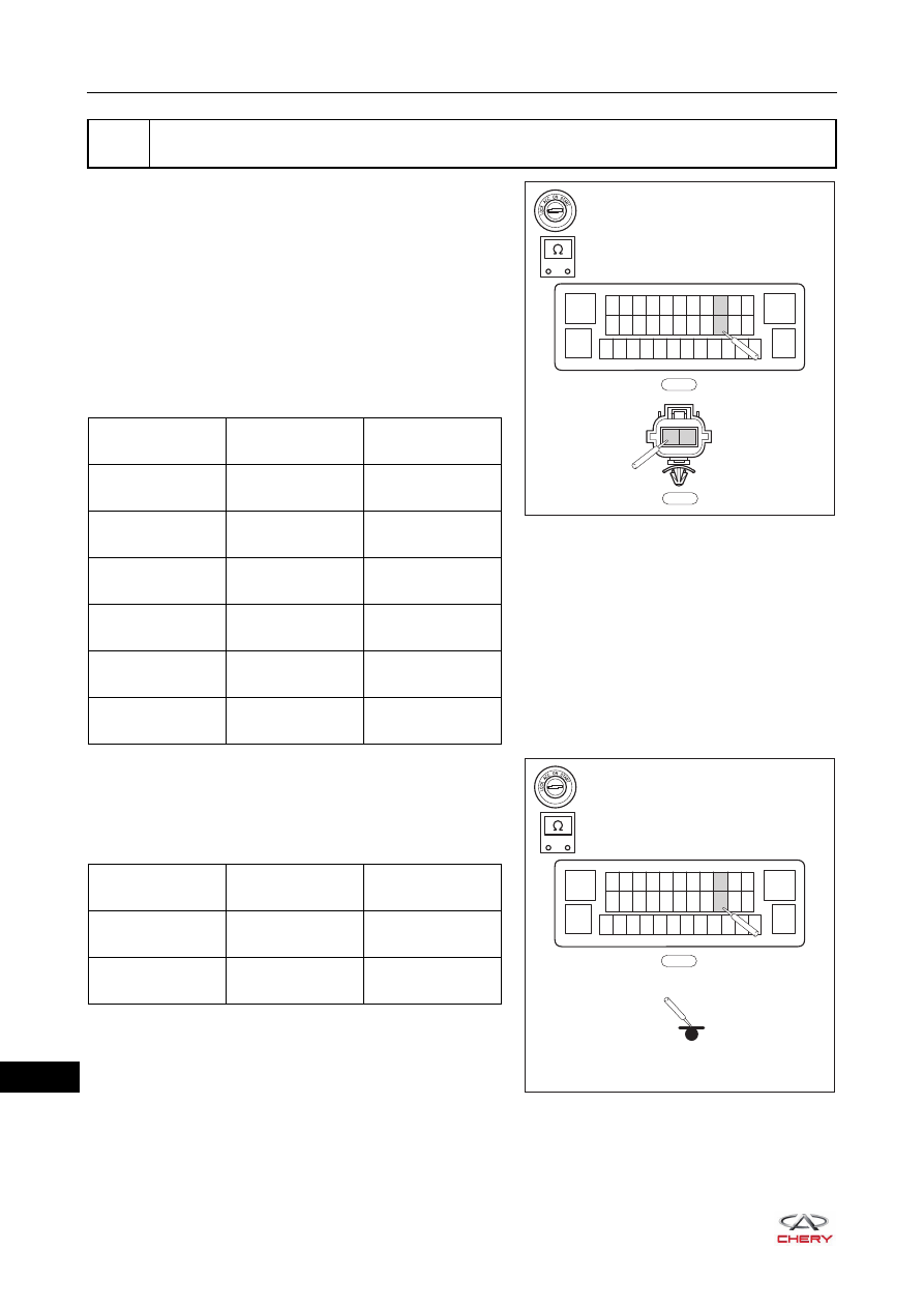
e. Using a digital multimeter, check for continuity between
the terminals of connector E-085 and connector E-036 to
check if there is an open in the wire harness and
connector according to the table below.
Standard Condition
f. Using a digital multimeter, check for continuity between
connector E-085 and body ground to check if the front
right wheel speed sensor is short to ground according to
the table below.
Standard Condition
5
Check wire harness and connector (front right wheel speed sensor - ABS control module
assembly)
RT21250260
E-085
13
12 11 10 9 8 7 6 5 4 3 2
24 23 22 21 20 19 18 17 16 15 14
37 36 35 34 33 32 31 30 29 28 27 26
1
38
25
-
+
E-036
1
2
Multimeter
Connection
Condition
Specified
Condition
E-085 (16) -
E-036 (1)
Always
Continuity
E-085 (4) -
E-036 (2)
Always
Continuity
E-085 (16) -
E-036 (2)
Always
No continuity
E-085 (4) -
E-036 (1)
Always
No continuity
E-036 (1) -
E-036 (2)
Always
No continuity
E-085 (4) -
E-085 (16)
Always
No continuity
RT21250270
E-085
13
12 11 10 9 8 7 6 5 4 3 2
24 23 22 21 20 19 18 17 16 15 14
37 36 35 34 33 32 31 30 29 28 27 26
1
38
25
-
+
Multimeter
Connection
Condition
Specified
Condition
E-085 (4) - Body
ground
Always
No continuity
E-085 (16) - Body
ground
Always
No continuity
Нет комментариевНе стесняйтесь поделиться с нами вашим ценным мнением.
Текст