Chery Tiggo 5 (T21). Service manual — part 120
07–
66
07
Removal & Installation - Front Mounting Assembly
1. Turn off all the electrical equipment and ignition switch.
2. Disconnect the negative battery cable.
3. Remove the engine lower protector assembly (
4. Support the transmission with a transmission carrier.
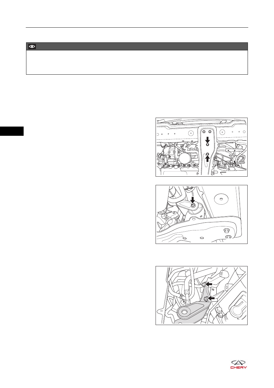
5. Remove the engine front mounting cushion assembly.
a. Remove 2 coupling bolts (arrow) between front
mounting cushion assembly and side rail welding
assembly.
(Tightening torque: 70 ± 5 N·m)
b. Remove the locking nut (arrow) for through bolt
between front mounting cushion assembly and front
mounting bracket, and remove the through bolt.
(Tightening torque: 70 ± 5 N·m)
c. Remove the engine front mounting cushion assembly.
6. Remove the engine front mounting bracket.
a. Remove 2 coupling bolts (arrow) between front
mounting bracket and transmission case.
(Tightening torque: 55 ± 5 N·m)
b. Remove the engine front mounting bracket from transmission case.
7. Installation is in the reverse order of removal.
CAUTION
Be sure to wear necessary safety equipment when repairing to prevent accidents.
Try to prevent body paint surface from being scratched during removal and installation.
RT21070630
RT21070640
RT21070650
07–
67
07
Removal & Installation - Left Mounting Assembly
1. Turn off all the electrical equipment and ignition switch.
2. Disconnect the negative battery cable.
3. Use an engine equalizer to hang the engine.
4. Remove the air filter assembly and its bracket (
5. Remove the battery (
).
6. Remove the battery tray and tray bracket (
).
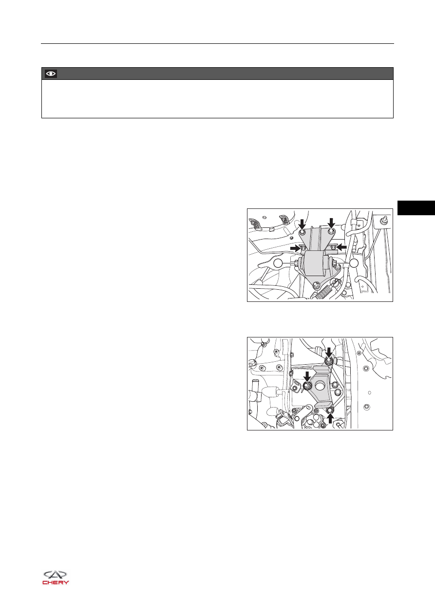
7. Remove the engine left mounting cushion assembly (for MT model).
a. Remove the locking nut (1) for through bolt between
left mounting cushion assembly and left mounting
bracket, and remove the through bolt (2).
(Tightening torque: 105 ± 10 N·m)
b. Remove 4 coupling bolts (arrow) between left
mounting cushion assembly and body.
(Tightening torque: 70 ± 5 N·m)
c. Remove the left mounting cushion assembly.
8. Remove the engine left mounting bracket (for MT model).
a. Remove 3 fixing nuts (arrow) between left mounting
bracket and transmission case.
(Tightening torque: 80 ± 6 N·m)
b. Remove the left mounting bracket.
CAUTION
Be sure to wear necessary safety equipment when repairing to prevent accidents.
Try to prevent body paint surface from being scratched during removal and installation.
1
2
RT21070660
RT21070670
07–
68
07
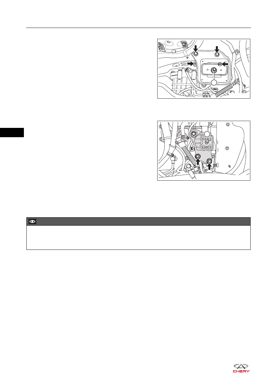
9. Remove the engine left mounting cushion assembly (for CVT model).
a. Remove the locking nut (1) from left mounting cushion
assembly.
(Tightening torque: 80 ± 6 N·m)
b. Remove 4 coupling bolts (arrow) between left
mounting cushion assembly and body.
(Tightening torque: 70 ± 5 N·m)
c. Remove the left mounting cushion assembly.
10.Remove the engine left mounting bracket (for CVT model).
a. Remove 2 fixing nuts (arrow) between left mounting
bracket and transmission case.
(Tightening torque: 80 ± 6 N·m)
b. Remove the coupling bolt (1) between left mounting
bracket and transmission case.
(Tightening torque: 80 ± 6 N·m)
c. Remove the left mounting bracket.
11.Installation is in the reverse order of removal.
Removal & Installation - Right Mounting Assembly
1. Turn off all the electrical equipment and ignition switch.
2. Disconnect the negative battery cable.
3. Remove the engine trim cover assembly (
).
4. Remove the engine lower right protector assembly (
).
5. Use an engine equalizer to hang the engine.
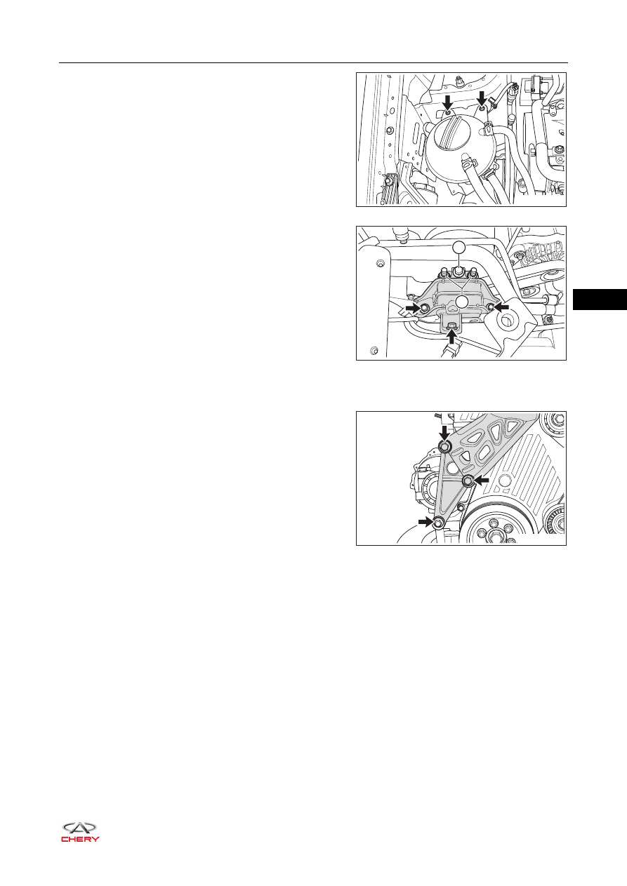
6. Remove the engine right mounting cushion assembly.
1
RT21070671
1
RT21070672
CAUTION
Be sure to wear necessary safety equipment when repairing to prevent accidents.
Try to prevent body paint surface from being scratched during removal and installation.
07–
69
07
a. Remove 2 fixing bolts (arrow) from expansion tank
and move the expansion tank to one side.
b. Remove the coupling bolt (1) and 2 coupling nuts (2)
between right mounting cushion assembly and right
mounting bracket.
(Tightening torque: 80 ± 6 N·m)
c. Remove 3 coupling bolts (arrow) between right
mounting cushion assembly and body.
(Tightening torque: 70 ± 5 N·m)
d. Remove the engine right mounting bracket.
7. Remove the engine right mounting bracket.
a. Remove 3 fixing bolts (arrow) from right mounting
cushion assembly.
(Tightening torque: 55 ± 5 N·m)
b. Remove the engine right mounting bracket assembly.
8. Installation is in the reverse order of removal.
RT21070680
1
2
RT21070690
RT21070691
Нет комментариевНе стесняйтесь поделиться с нами вашим ценным мнением.
Текст