Chery Tiggo 5 (T21). Service manual — part 366
32–
55
32
a. Turn ignition switch to LOCK, disconnect the negative
battery cable and wait for at least 90 seconds.
b. Disconnect the instrument panel wire harness connector
I-006 and SRS control module assembly connector I-046
(*1).
c. Using a digital multimeter, check for continuity between
the terminals of connector I-006 and connector I-046
according to the table below.
Standard Condition
a. Turn ignition switch to LOCK, disconnect the negative
battery cable and wait for at least 90 seconds.
b. Disconnect front passenger seat belt reminder switch
connector B-049 and SRS control module assembly
connector I-046/B-072.
c. Using a digital multimeter, check for continuity between
the terminals of connector B-049 and connector I-046/B-
072 according to the table below.
Standard Condition
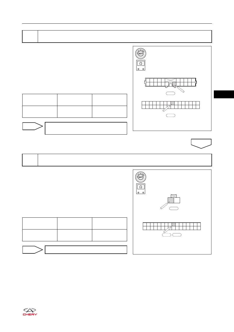
4
Check front passenger seat belt reminder switch wire harness and connector (SRS control
module assembly - instrument panel wire harness connector)
-
+
RT21320370
32
31
30
29
28
16
15
14
13
12
11
10
9
8
7
6
5
4
3
2
1
27
26
25
24
23
22
21
20
19
18
17
I-046
1
2
3
4
5
6
7
8
9
10
11
12
13
14
15
16
17
18
19
20
21
22
I-006
Multimeter
Connection
Condition
Specified
Condition
I-006 (16) - I-046
(25)
Always
Continuity
Replace instrument panel wire harness
and connector
NG
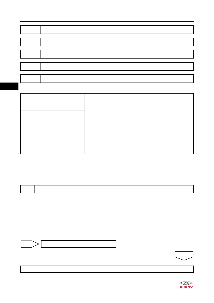
5
Check wire harness and connector (SRS control module assembly - front passenger seat
belt reminder switch)
OK
-
+
RT21320371
32
31
30
29
28
16
15
14
13
12
11
10
9
8
7
6
5
4
3
2
1
27
26
25
24
23
22
21
20
19
18
17
B-072
I-046
1
2
B-049
Multimeter
Connection
Condition
Specified
Condition
B-049 (1) - I-046/
B-072 (25)
Always
Continuity
Replace body wire harness and connector
NG
32–
56
32
Self-diagnosis Detection Logic
HINT:
When performing electrical diagnosis and test, always refer to the relevant circuit diagram for the special
circuit and component information.
Diagnosis Procedure
a. Turn ignition switch to LOCK.
b. Disconnect the negative battery cable and wait for at least 90 seconds.
c. Connect the negative battery cable.
d. Turn ignition switch ON.
e. Use X-431 3G diagnostic tester (the latest software) to record and clear the DTCs stored in the
supplemental restraint system.
f. Turn ignition switch to LOCK and wait for a few seconds.
g. Turn ignition switch ON, and then select "Read Code".
DTC
B1210-00 Front Deployment
DTC
B1211-00 BT Deployment
DTC
B125A-00 Crash Counter Reached Max
DTC
B1240-96 ICM Airbag Lamp Failed
DTC
B1251-49 Electronic Control Unit (ECU), Internal Electronic Failure
DTC Code
DTC Definition
DTC Detection
Condition
Warning Light
Condition
Possible Cause
B1210-00
Front Deployment
Ignition switch ON
ON
SRS control
module assembly
B1211-00
BT Deployment
B125A-00
Crash Counter
Reached Max
B1240-96
ICM Airbag Lamp
Failed
B1251-49
Electronic Control Unit
(ECU), Internal
Electronic Failure
1
Check SRS control module assembly
Replace SRS control module assembly
NG
OK
Malfunction has been solved and system operates normally
32–
57
32
DTC
B1250-16 Battery Voltage Circuit Voltage Below Threshold
DTC
B1250-17 Battery Voltage Circuit Voltage Above Threshold
32–
58
32
1
2
3
4
5
6
7
8
9 10 11 12
13
85
85
87
87 30
87 30
30
86
86
85
86
14 15 16 17 18 19 20 21 22 23 24
25
27
26
32
31
30
29
28
16
15
14
13
12
11
10
9
8
7
6
5
4
3
2
1
27
26
25
24
23
22
21
20
19
18
17
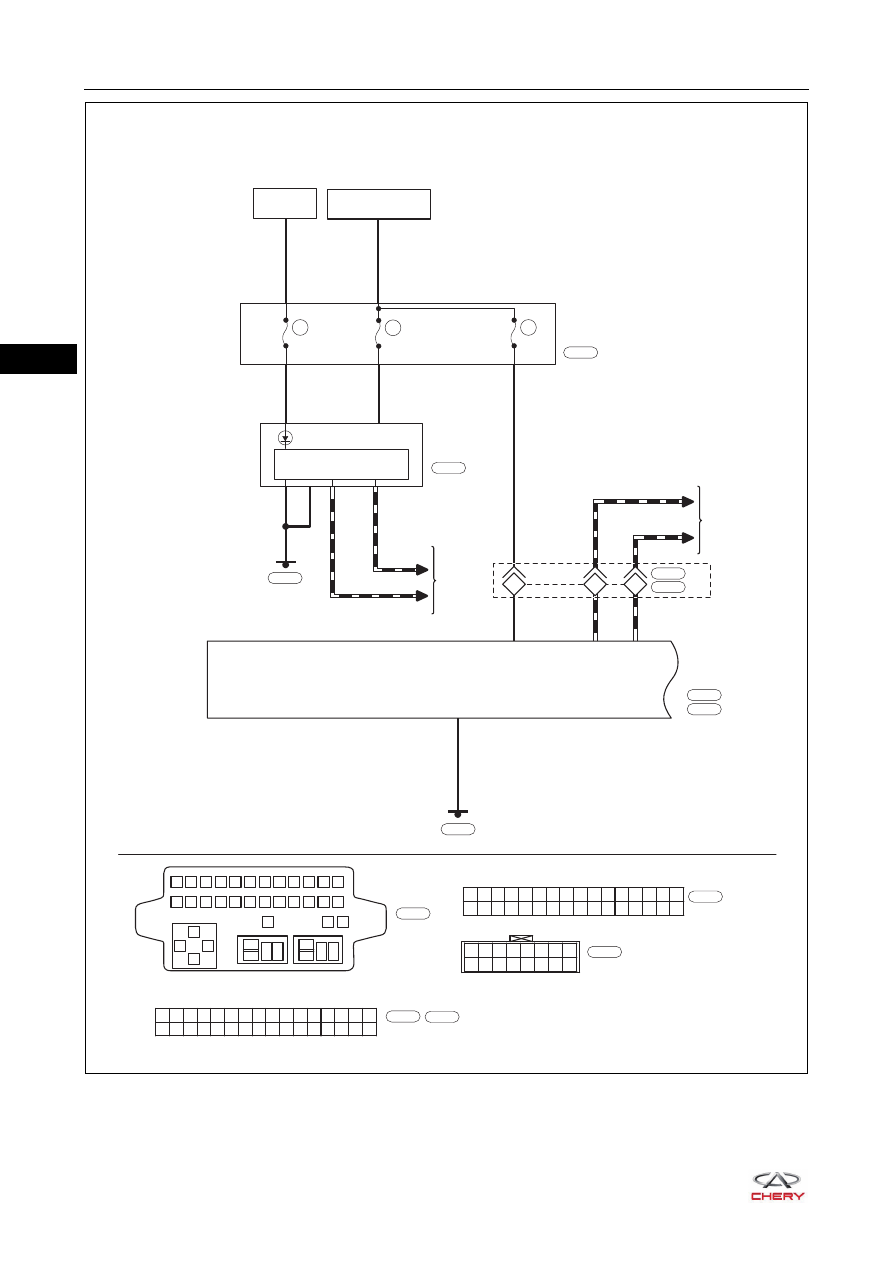
IGNITION SWITCH
ON OR START
10A
RF08
10A
23
11
R
B
OB
O
P
13
3
5
29
30
GND
MICROPROCESSOR
AIRBAG
INSTRUMENT
CLUSTER
RF06
SRS
CONTROL
MODULE
BATTERY
10A
6
RF23
TO CAN
SYSTEM
INSTRUMENT
PANEL FUSE
AND RELAY BOX
I-003
CAN-L2
CAN-H2
CAN-L1 CAN-H1
32
31
30
29
28
16
15
14
13
12
11
10
9
8
7
6
5
4
3
2
1
27
26
25
24
23
22
21
20
19
18
17
B
I-007
I-007
Gr
I-046
I-046
L
I-015
I-015
B
I-045
16
8
R
R
OB
O
OB
O
1
17
2
TO CAN
SYSTEM
I-036
B-055
4
9
10
*2
16 15 14 13 12 11 10
8
7
6
5
4
3
2
1
9
W
I-036
*2: SRS control module connector is B-072
*1: SRS control module connector is I-046
B-072
B
B-072
ET21320100
Нет комментариевНе стесняйтесь поделиться с нами вашим ценным мнением.
Текст