Chery Tiggo 5 (T21). Service manual — part 360
32–
31
32
DTC
B0070-11
Belt Pretensioner Front Driver Loop Circuit Short to
Ground
DTC
B0070-12
Belt Pretensioner Front Driver Loop Circuit Short to
Battery
DTC
B0070-1A
Belt Pretensioner Front Driver Loop Circuit Resistance
Below Threshold
DTC
B0070-1B
Belt Pretensioner Front Driver Loop Circuit Resistance
Above Threshold
DTC
B0070-1C
Belt Pretensioner Front Driver Loop Circuit Voltage Out
of Range
32–
32
32
ET21320060
32
31
30
29
28
16
15
14
13
12
11
10
9
8
7
6
5
4
3
2
1
27
26
25
24
23
22
21
20
19
18
17
Gr
I-046
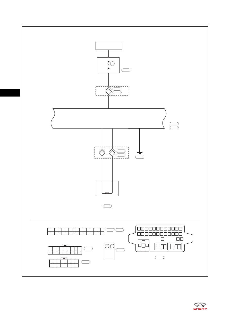
SRS
CONTROL
MODULE
I-046
IGNITION SWITCH
ON OR START
10A
RF08
INSTRUMENT
PANEL FUSE
AND RELAY BOX
I-007
B
I-045
16
1
2
3
4
5
6
7
8
9 10 11 12
13
85
85
87
87 30
87 30
30
86
86
85
86
14 15 16 17 18 19 20 21 22 23 24
25
27
26
B
I-007
18 17 16 15 14 13 12 11 10
9
8
7
6
5
4
3
2
1
1
2
-
+
W
I-035
B
B-034
LW
LW
LB
LB
+
-
2
1
10
9
1
2
B-072
I-035
B-059
DRIVER SEAT BELT
PRE-TENSIONER
B-034
*1
*2: SRS control module connector is B-072
*1: SRS control module connector is I-046
B
B-072
8
R
R
1
4
I-036
B-055
*2
16 15 14 13 12 11 10
8
7
6
5
4
3
2
1
9
W
I-036
32–
33
32
Self-diagnosis Detection Logic
HINT:
When performing electrical diagnosis and test, always refer to the relevant circuit diagram for the special
circuit and component information.
Diagnosis Procedure
a. Turn ignition switch to LOCK, disconnect the negative battery cable and wait for at least 90 seconds.
b. Disconnect driver seat belt pretensioner connector, and connect the new driver seat belt pretensioner
connector to connector B-034.
c. Reconnect the negative battery cable and wait for a few seconds.
d. Turn ignition switch ON and wait for at least 90 seconds.
e. Use X-431 3G diagnostic tester to clear the DTCs.
f. Turn ignition switch to LOCK.
g. Turn ignition switch ON and wait for at least 90 seconds.
h. Use X-431 3G diagnostic tester to check if the DTCs are still output.
DTC Code
DTC Definition
DTC Detection
Condition
Warning Light
Condition
Possible Cause
B0070-11
Belt Pretensioner Front
Driver Loop Circuit
Short to Ground
Ignition switch ON
ON
Driver seat belt
pretensioner
Wire harness and
connector
SRS control
module assembly
B0070-12
Belt Pretensioner Front
Driver Loop Circuit
Short to Battery
B0070-1A
Belt Pretensioner Front
Driver Loop Circuit
Resistance Below
Threshold
B0070-1B
Belt Pretensioner Front
Driver Loop Circuit
Resistance Above
Threshold
B0070-1C
Belt Pretensioner Front
Driver Loop Circuit
Voltage Out of Range
1
Check driver seat belt pretensioner
WARNING
Never measure the driver seat belt pretensioner directly, otherwise, it may cause serious personal injury
due to accidental deployment of the airbag.
Replace driver seat belt pretensioner
NG
OK
32–
34
32
Use circuit diagram as a guide to perform the following procedures:
a. Turn ignition switch to LOCK, disconnect the negative battery cable and wait for at least 90 seconds.
b. Disconnect the driver seat belt pretensioner connector B-034 and SRS control module assembly
connector I-046/B-072.
c. Disconnect the body wire harness connector B-059 and instrument panel wire harness connector I-035
(*1).
d. Check if wire harnesses are worn, pierced, pinched or partially broken.
e. Check for broken, bent, protruded or corroded terminals.
f. Check if related connector terminal contact pins are in good condition.
a. Turn ignition switch to LOCK, disconnect the negative
battery cable and wait for at least 90 seconds.
b. Disconnect the SRS control module assembly connector
I-046/B-072.
c. Disconnect the driver seat belt pretensioner connector
B-034.
d. Connect the negative battery cable and wait for a few
seconds.
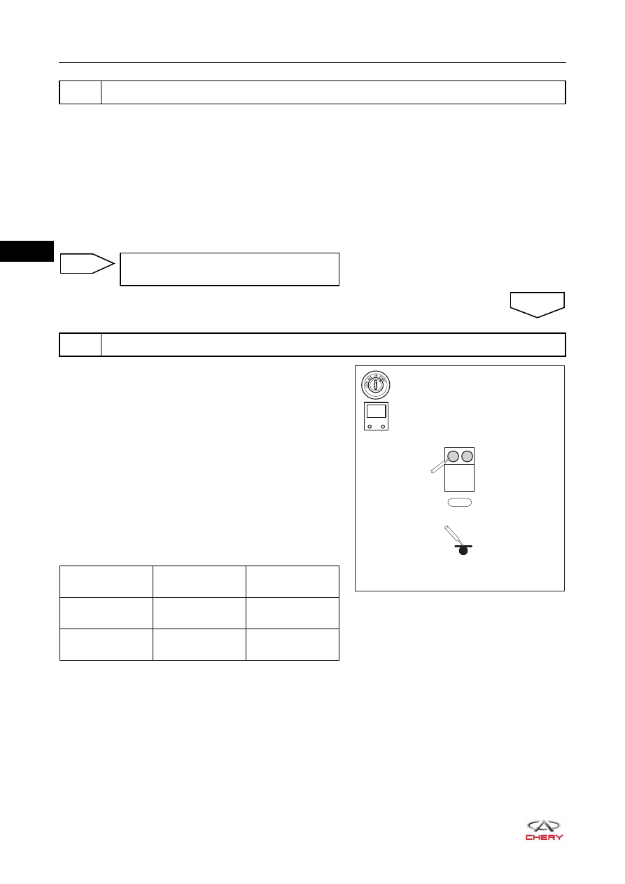
e. Turn ignition switch ON.
f. Using a digital multimeter, measure the voltage between
driver seat belt pretensioner connector B-034 and body
ground to check for a short circuit to power supply
according to the table below.
Standard Voltage
2
Check wire harness and connector
Repair or replace instrument panel/body
wire harness and connector
3
Check driver seat belt pretensioner control circuit
NG
OK
RT21320240
-
+
V
1
2
-
+
B-034
Multimeter
Connection
Condition
Specified
Condition
B-034 (1) - Body
ground
Ignition switch ON
Below 1 V
B-034 (2) - Body
ground
Ignition switch ON
Below 1 V
Нет комментариевНе стесняйтесь поделиться с нами вашим ценным мнением.
Текст