Chery Tiggo 5 (T21). Service manual — part 194
17–
30
17
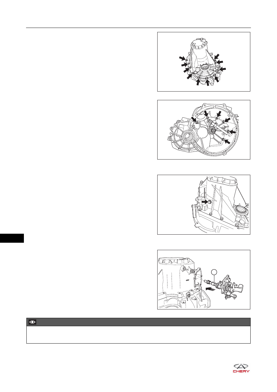
b. Install the transmission case fixing bolts (arrow) and
tighten them.
(Tightening torque: 25 ± 2 N·m)
c. Install the clutch case fixing bolts (arrow) and tighten
them.
(Tightening torque: 25 ± 2 N·m)
9. Install the reverse idler gear shaft locating bolt.
a. Install the reverse idler gear shaft locating bolt (arrow)
to the transmission case.
(Tightening torque: 40 ± 4 N·m)
10.Install the gear shift mechanism.
a. Install the gear shift mechanism (1) to the
transmission case.
RT21170250
RT21170240
RT21170230
1
RT21170380
CAUTION
Clean the engagement portion of shifter case and transmission case, and apply seal gum evenly.
17–
31
17
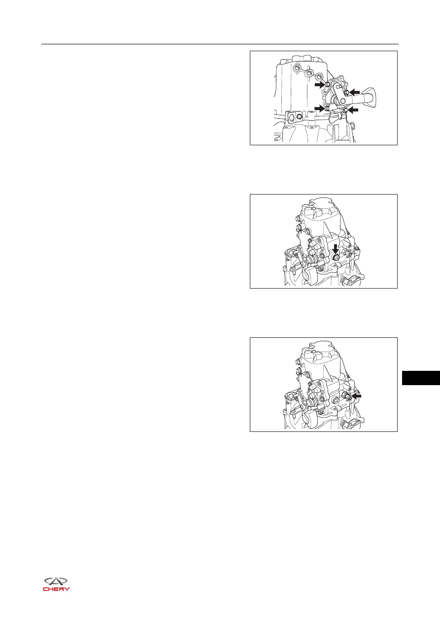
b. Install the coupling bolts (arrow) between gear shift
mechanism and transmission case.
(Tightening torque: 25 ± 2 N·m)
11.Install the gear shift mechanism locating bolt.
HINT:
Apply thread adhesive to thread before installation.
a. Install the gear shift mechanism locating bolt (arrow)
to the transmission case.
(Tightening torque: 35 ± 5.25 N·m)
12.Install the back-up light switch.
HINT:
Apply thread adhesive to thread before installation.
a. Install the back-up light switch (arrow) to the
transmission case.
(Tightening torque: 20 ± 2 N·m)
RT21170200
RT21170180
RT21170190
17–
32
17
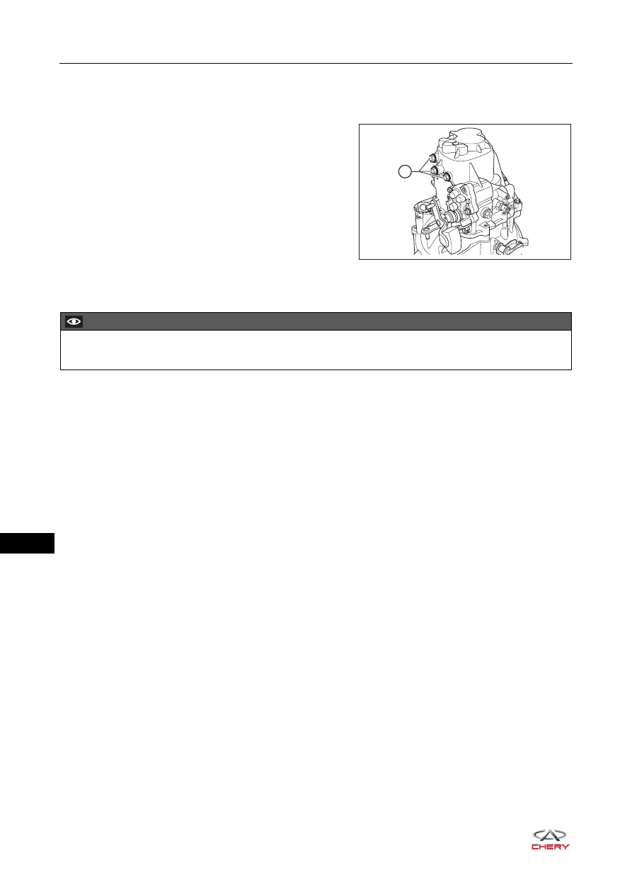
13.Install the shift shaft locating bolt.
HINT:
Apply thread adhesive to thread before installation.
a. Install the shift shaft locating bolts (1) to the
transmission case.
(Tightening torque: 35 ± 5.25 N·m)
Installation
Installation is in the reverse order of removal.
1
RT21171070
CAUTION
After installation, add transmission oil and check the oil level.
17–
33
17
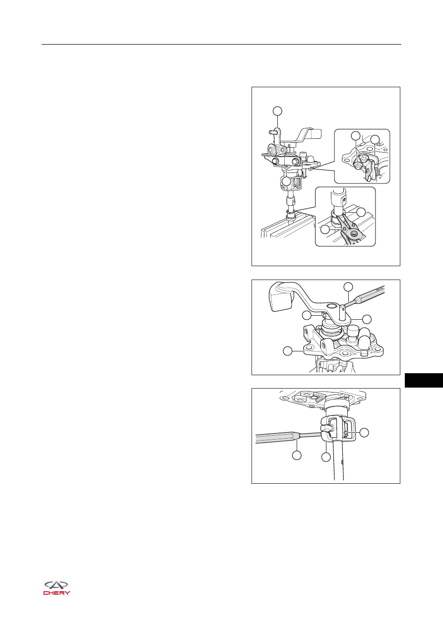
Gear Shift Mechanism
Disassembly
1. Loosen the shift arm bracket bolts (A).
(Tightening torque: 25 ± 2 N·m)
2. Remove the shift arm bracket (1).
3. Using snap spring calipers (2), remove the snap ring (3).
4. Loosen the fixing bolts (B) of reverse gear lock
mechanism.
(Tightening torque: 18 ± 2 N·m)
5. Remove the reverse gear lock mechanism (4).
6. Tap out the dowel pin (2) with a punch (1).
7. Remove the shift arm (3) and plate (4).
8. Tap out the dowel pin (2) with a punch (1).
9. Remove the shift finger (3).
RT21170400
B
A
1
4
3
2
3
2
4
1
RT21170410
2
1
3
RT21170420
Нет комментариевНе стесняйтесь поделиться с нами вашим ценным мнением.
Текст