Chery Tiggo 5 (T21). Service manual — part 101

06–
246
06
Installation
Installation is in the reverse order of removal.
CAUTION
Never allow any kinds of gasket and washer between sensor and engine block. Only the metal part of
sensor can contact with the engine block directly.
DO NOT apply lubricant, grease or seal gum when installing knock sensor. Keep engine block clean and
dry, and never allow any foreign matter (such as oil) on the installation area of knock sensor.
Never tap knock sensor when installing it.

06–
247
06
Oxygen Sensor
Description
This vehicle is equipped with two oxygen sensors (upstream oxygen sensor and downstream oxygen sensor).
Oxygen sensors continually monitor the oxygen concentration in exhaust gas.
Operation
The oxygen sensor generates voltage depending on the oxygen content in exhaust gas. The sensor
generates low voltage when oxygen content is high, and high voltage when oxygen content is low. Therefore,
the sensor acts as a rich-lean switch.
The oxygen sensor is equipped with a heating element that keeps sensor at proper operating temperature
under all operating conditions.
Upstream Oxygen Sensor
The input signal from upstream heated oxygen sensor informs Engine Control Module (ECM) of the oxygen
content in exhaust gas. Based on this input signal, Engine Control Module (ECM) adjusts air-fuel ratio finely
by adjusting injector pulse width.
Downstream Oxygen Sensor
The downstream heated oxygen sensor signal is used to detect the catalytic converter deterioration. As
converter deteriorates, the signal from downstream oxygen sensor begins to match upstream oxygen sensor
signal except for a slight time delay. By comparing the signal from upstream heated oxygen sensor to the
signal from downstream oxygen sensor, Engine Control Module (ECM) calculates the efficiency of catalytic
converter.
Removal & Installation - Upstream Oxygen Sensor
(
)
Removal & Installation - Downstream Oxygen Sensor
(
)
06–
248
06
Camshaft Position Sensor
Description
This vehicle is equipped with an intake camshaft position sensor and an exhaust camshaft position sensor,
which are installed on cylinder head cover.
Operation
The camshaft position sensor is a Hall type sensor and a sensor plate is installed on camshaft. When the
sensor plate is in high teeth, the applicable circuit output is low; when the sensor plate is in missing teeth, the
applicable circuit output is high. As a result, the crankshaft phase information is provided to Engine Control
Module (ECM) so that the compression top dead center and exhaust top dead center of crankshaft can be
distinguished.
Removal
1. Turn off all electrical equipment and ignition switch.
2. Disconnect negative battery cable.
3. Remove engine trim cover.
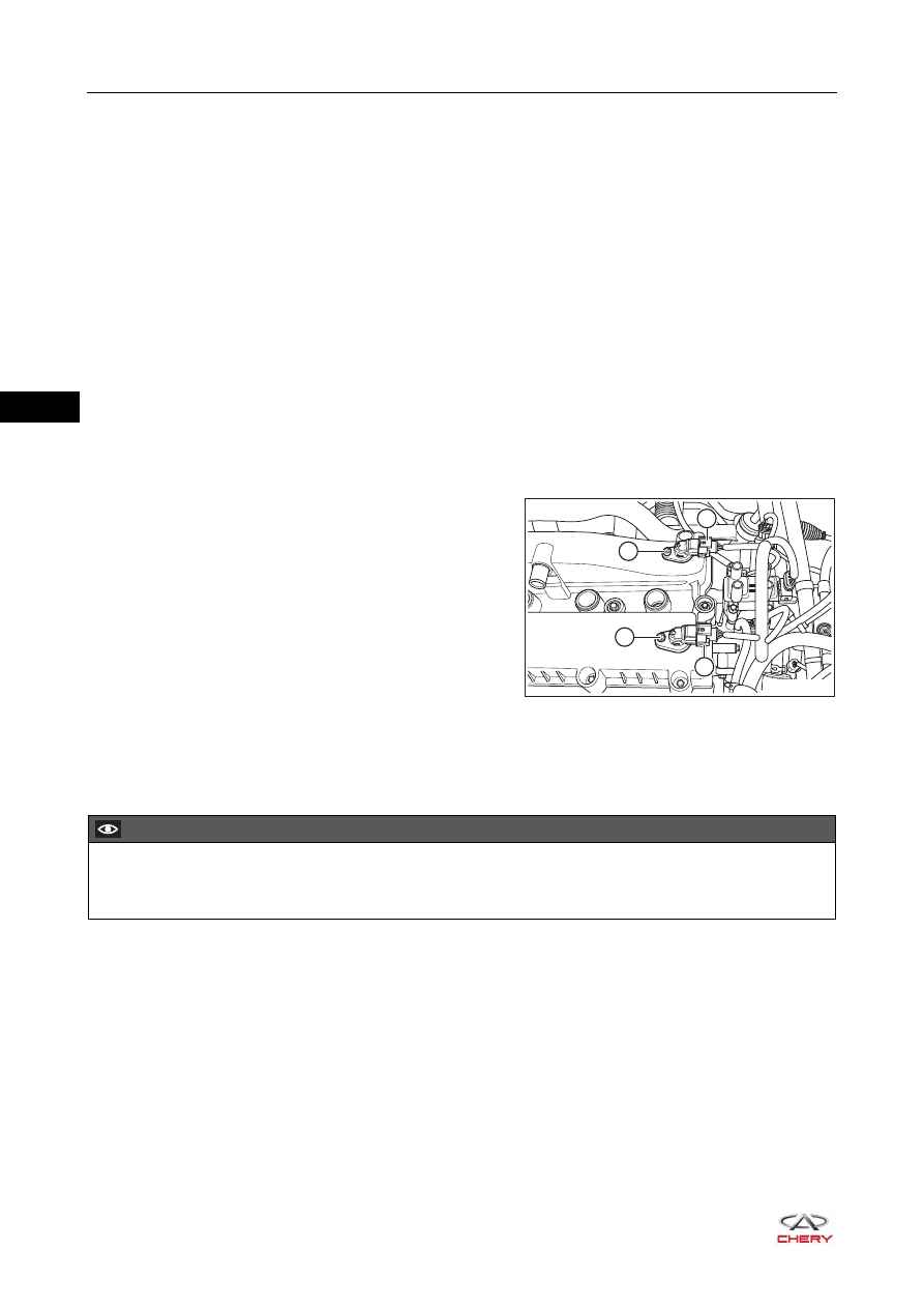
4. Remove camshaft position sensor.
a. Disconnect intake camshaft position sensor connector
(1) and exhaust camshaft position sensor connector
(2).
b. Remove intake camshaft position sensor fixing bolt (3)
and exhaust camshaft position sensor fixing bolt (4).
(Tightening torque: 8 ± 0.5 N·m)
c. Remove intake camshaft position sensor and exhaust camshaft position sensor.
Installation
Installation is in the reverse order of removal.
RT21060350
4
3
2
1
CAUTION
The sensor should be pressed into mounting hole. Never use tools (such as a hammer) to strike the
sensor into mounting hole forcibly.
06–
249
06
Engine Speed Sensor
Description
The engine speed sensor is installed on clutch case, against flywheel teeth. It is used to detect the speed and
position of crankshaft.
Operation
The engine speed sensor operates by using magnetoelectric effect. When crankshaft rotates, it drives
flywheel to rotate. The flywheel teeth will cut the magnetic line of sensor, and change of magnetic flux causes
both ends of sensor coil to generate output voltage with a certain frequency that is sent to Engine Control
Module (ECM). And the output signal can indicate the speed and position of crankshaft.
Removal
1. Turn off all electrical equipment and ignition switch.
2. Disconnect negative battery cable.
3. Remove engine trim cover.
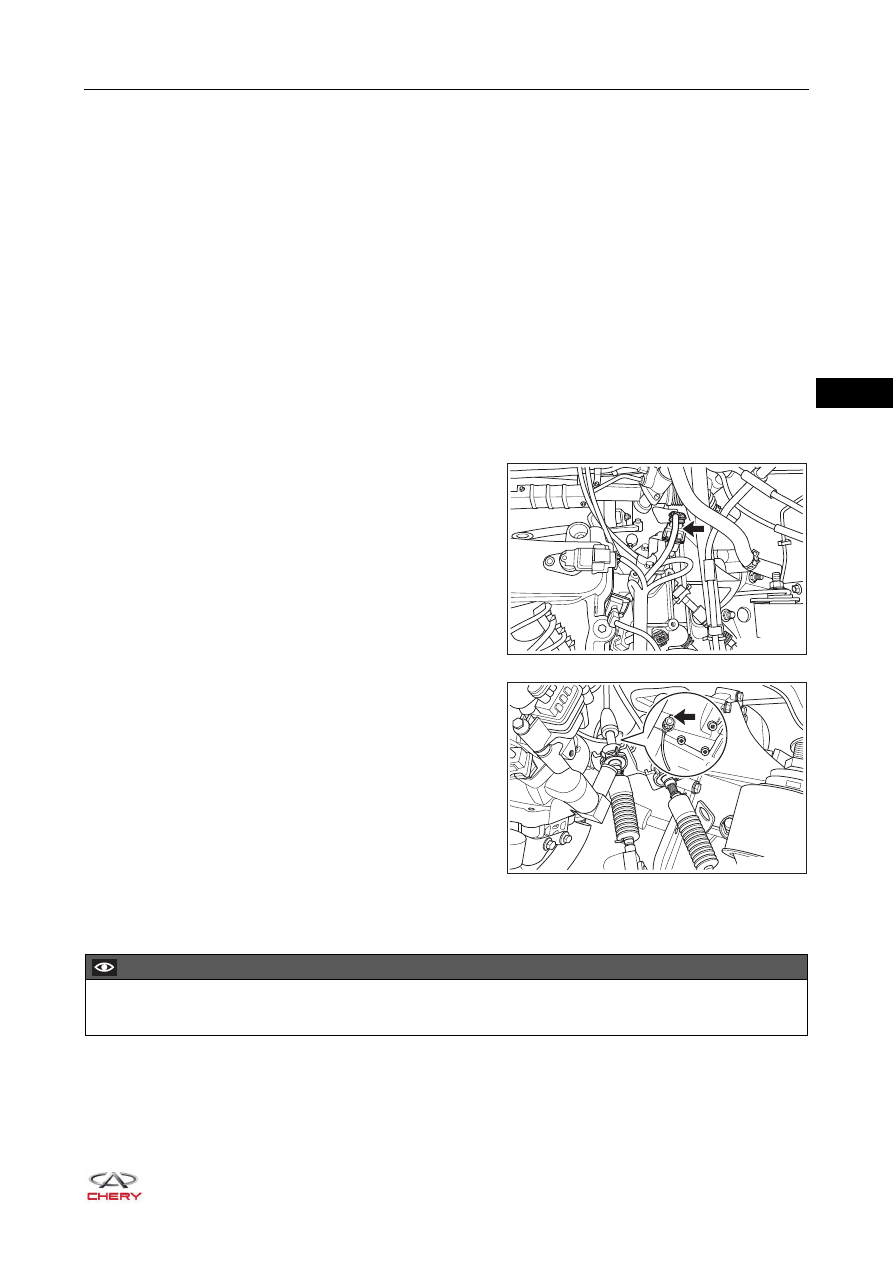
4. Remove engine speed sensor.
a. Disconnect engine speed sensor connector (arrow),
and move away the engine speed sensor cable from
bracket.
b. Remove engine speed sensor fixing bolt and engine
speed sensor.
(Tightening torque: 8 ± 2 N·m)
Installation
Installation is in the reverse order of removal.
RT21060360
RT21060370
CAUTION
Press in the engine speed sensor rather than tap when installing it.
Нет комментариевНе стесняйтесь поделиться с нами вашим ценным мнением.
Текст