Jaguar XJ (X350). Service manual — part 515

Camshaft bearing caps retaining bolts
A –
–
Camshaft position sensor retaining bolt
10 –
89
Camshaft hub retaining bolts
A –
–
Camshaft pulley retaining bolts
23 17 –
Crankshaft pulley retaining bolt
A –
–
Crankshaft position sensor retaining bolt
5
–
44
Coolant inlet housing
10 –
89
Cylinder head retaining bolts
A –
–
Engine mount retaining nuts to crossmember
63 46 –
Engine mount bracket to engine mount retaining nut
48 35 –
Engine mount bracket to engine block retaining bolts
90 66 –
Engine wiring harness retaining bracket
4
–
35
Exhaust manifold heat shield retaining bolts
10 –
89
Exhaust manifold retaining bolts
23 17 –
Flexplate retaining bolts
A –
–
Fuel injection pump
23 17 –
Fuel injection pump pulley retaining nut
50 37 –
Fuel injector retaining bolts
10 –
89
Generator retaining bolts
47 35 –
Generator mount bracket retaining bolts
23 17 –
Glow plugs
10 –
89
Knock sensor retaining nuts
20 15 –
Oil cooler to cylinder block retaining bolt
10 –
89
Oil level indicator tube retaining bolt
10 –
89
Oil pan retaining bolts
10 –
89
Oil pump to engine block retaining bolts
10 –
89
Oil pan drain plug
25 18 –
Oil separator pipe retaining bolts
10 –
89
Oil filter
25 18 –
Piston cooling jet retaining bolt
10 –
89
Power steering bracket retaining bolts
23 17 –
Power steering pump retaining bolts
22 16 –
Primary timing chain tensioner retaining bolts
12 9
–
Starter motor retaining bolts
48 35 –
Timing belt tensioner retaining bolt
24 18 –
Timing belt idler pulley retaining bolt
45 33 –
Water pump retaining bolts
10 –
89
Water pump pulley retaining bolts
24 18 –

Water pump outlet pipe retaining bolts
10 –
89
Valve cover retaining bolts
10 –
89
Vacuum pump retaining bolts
23 17 –
Vacuum pump retaining nuts
13 10 –
www.
Description and operation
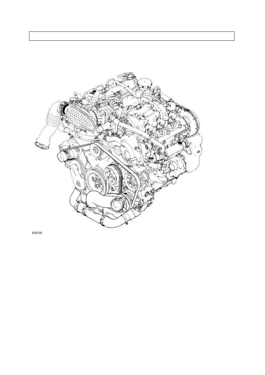
Engine
The 2.7 litre engine consists of a six cylinder 60-degree 'Enclosed Vee' configuration liquid cooled
Compacted Graphite Iron (CGI) with the cylinder bores machined directly into the block.
Viewed from the driving position, the right-hand cylinder bank is numbered 1 to 3, from the front of
the vehicle and the left-hand cylinder bank are numbered 4 to 6, from the front of the vehicle.
Knock Sensors
The knock sensor registers increased vibrations which occur due to increased combustion noise. The
ECM uses the signal as a correction factor for calculating the quantity of fuel to be injected during the
injection phase.
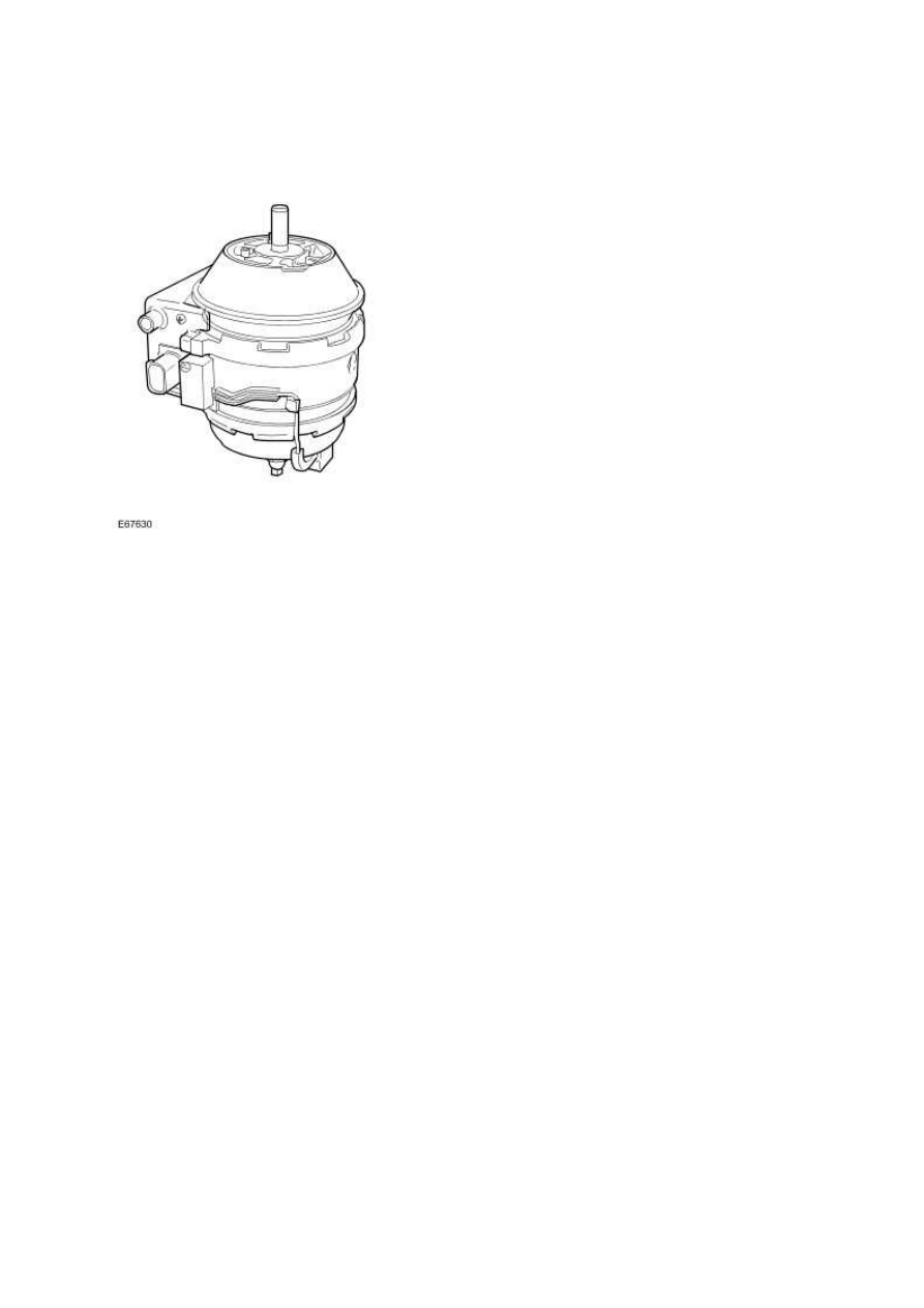
Active Engine Mounts
The function of the engine mounts is to support the engine, whilst also isolating vibrations
transmitted from the engine to the vehicle body.
The active engine mounts are functional only when the engine is at idle, as this is when the engine
high frequency vibrations are the dominant vibrations noticeable to the vehicle's occupants.
The mechanical construction of the active engine mounts is similar to the passive hydraulic engine
mounts, but with the added element of an internal shaker mechanism. The shaker mechanism of the
active engine mounts works on the same concept as a speaker diaphragm to move the top section of
the active engine mounts to oppose the vibrations generated by the engine. The active engine
mounts mechanism estimates the vibration caused by fluctuations in the engine crank rotation and
isolates these vibrations by generating additional vibrations through the internal shaker mechanism.
The result gives vibration isolation and reduction of chassis vibration.
To ensure accurate vibration suppression the active engine mounts have an electronic control
module attached to the body and an accelerometer attached to the base.
www.
Нет комментариевНе стесняйтесь поделиться с нами вашим ценным мнением.
Текст