Jaguar XJ (X350). Service manual — part 263

-> No
REPAIR the short circuit. For additional information, refer to the wiring diagrams. Clear the DTC, test
the system for normal operation by driving the vehicle to a speed greater than 20 Kph (12.5 mph) for
more than 3 seconds.
G531322t76 : CHECK THE YAW RATE SENSOR AND ACCELEROMETER CAN -
CIRCUIT FOR HIGH RESISTANCE
1. Key off. 2. Disconnect the ABS module connector, EC030. 3. Key on, engine off. 4. Measure the
resistance between:
IP023, harness side EC030, harness side
Pin 01
Pin 19
•
Is the resistance less than 10 ohms?
-> Yes
GO to Pinpoint Test
G531322t77
.
-> No
REPAIR the high resistance circuit. For additional information, refer to the wiring diagrams. Clear the
DTC, test the system for normal operation by driving the vehicle to a speed greater than 20 Kph (12.5
mph) for more than 3 seconds.
G531322t77 : CHECK THE YAW RATE SENSOR AND ACCELEROMETER CAN +
CIRCUIT FOR HIGH RESISTANCE
1. Measure the resistance between:
IP023, harness side EC030, harness side
Pin 02
Pin 18
•
Is the resistance less than 10 ohms?
-> Yes
GO to Pinpoint Test
G531322t78
.
-> No
REPAIR the high resistance circuit. For additional information, refer to the wiring diagrams. Clear the

DTC, test the system for normal operation by driving the vehicle to a speed greater than 20 Kph (12.5
mph) for more than 3 seconds.
G531322t78 : CHECK THE YAW RATE SENSOR AND ACCELEROMETER CAN +
AND - CIRCUITS FOR SHORT CIRCUIT TO EACH OTHER
1. Measure the resistance between:
IP023, harness side IP023, harness side
Pin 02
Pin 01
•
Is the resistance greater than 10 Kohms?
-> Yes
An intermittent fault may be present in the wiring harness. Visually check for chaffed wires or other
physical damage to the harness.
-> No
REPAIR the short circuit. For additional information, refer to the wiring diagrams. Clear the DTC, test
the system for normal operation by driving the vehicle to a speed greater than 20 Kph (12.5 mph) for
more than 3 seconds.
www.
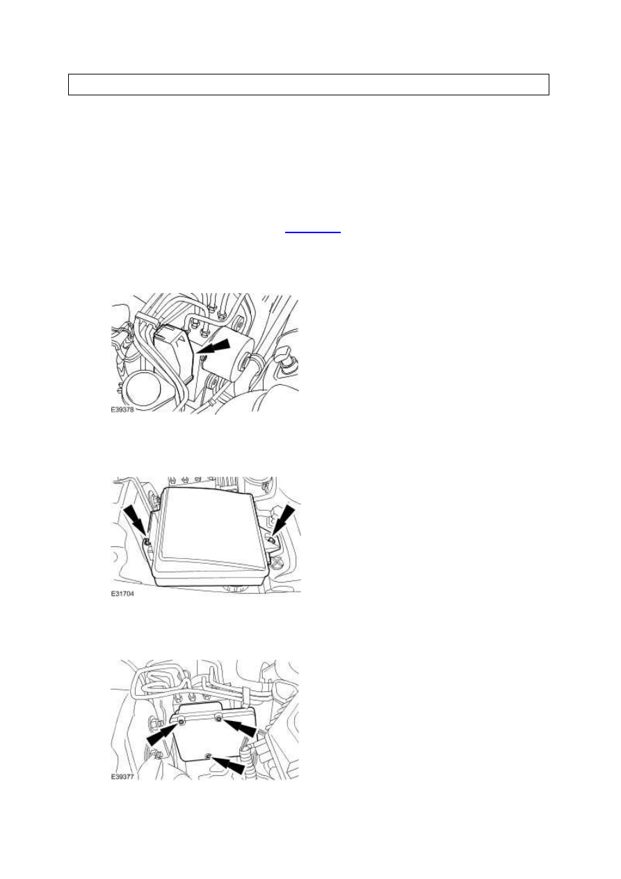
Removal and installation
Anti-Lock Brake System (ABS) Module
(70.60.02)
Removal
1 . Disconnect the battery ground cable.
2 . Disconnect the hydraulic control unit electrical connector.
3 . Detach the engine compartment battery junction box.
4 . Remove the ABS module.
Installation
1 . To install, reverse the removal procedure.
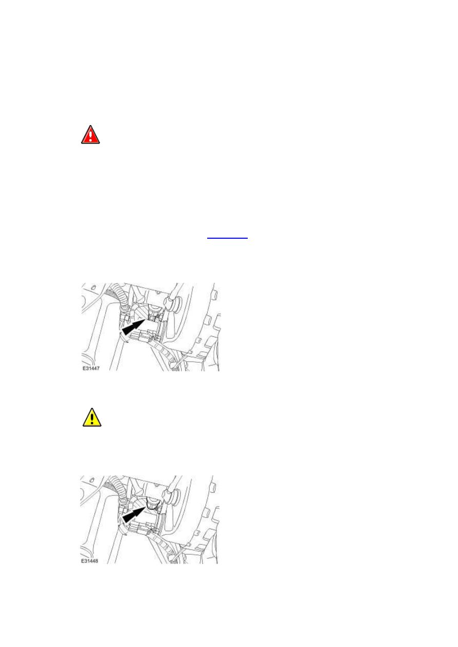
Brake Master Cylinder Pressure
Transducer
Removal
1
.
WARNING: Brake fluid contains polyglycol ethers and polyglycols. Avoid contact
with the eyes. Wash hands thoroughly after handling, as prolonged contact may cause
irritation and dermatitis. If brake fluid contacts the eyes, flush the eyes with cold water or
eyewash solution and seek medical attention. If taken internally do not induce vomiting,
seek immediate medical attention. Failure to follow these instructions may result in
personal injury.
Disconnect the battery ground cable.
2 . Disconnect the brake master cylinder primary pressure transducer electrical connector.
3
.
CAUTION: If brake fluid is spilt on the paintwork, the effected area must be
immediately washed down with cold water.
Remove the brake master cylinder primary pressure transducer.
www.
Нет комментариевНе стесняйтесь поделиться с нами вашим ценным мнением.
Текст