Jaguar XJ (X350). Service manual — part 1190
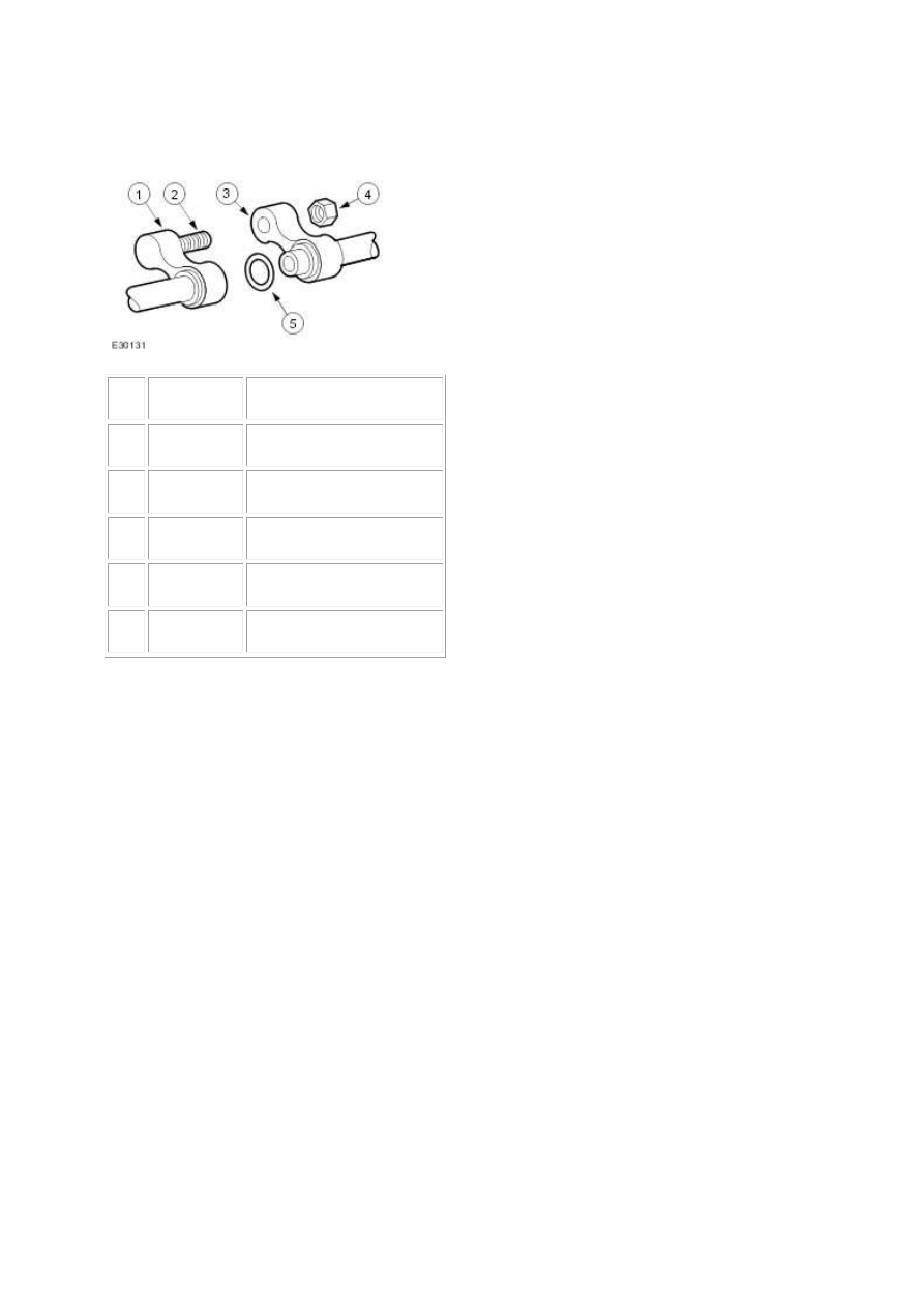
Air Conditioning Line Peanut Fitting
Peanut Fitting Assembly
Item
Part Number
Description
1
—
Female air conditioning line
2
—
Stud
3
—
Male air conditioning line
4
—
Retaining nut
5
—
O-ring seal
The connections between the air conditioning (A/C) condenser core/receiver drier and the
connections between the lines use peanut fittings.
•
The male and female line of the peanut fitting are retained with a nut.
•
An O-ring seal is installed around the tube on the male line.
•
The female line is welded to the tube and is not adjustable.
•
Support the female line with a wrench to prevent the twisting of the tubes.
•
The male line will pivot around the tube to allow for alignment with the female line during
assembly.
•
When correctly assembled, the mating surfaces of the male and female fittings should be
flush.
Blower motor
The blower motor pulls air from the air inlet and forces it into the heater core and evaporator core
housing where it is mixed and distributed. The blower motor has eleven speeds (vehicles with
telematics have seven speeds) and is controlled by the remote climate control module (RCCM).
Air conditioning refrigerant
The R-134a air conditioning system uses a hydrofluorocarbon (HFC) non-CFC based refrigerant. R-
134a requires the use of Jaguar compressor oil or equivalent meeting Jaguar specification. Do not use
R-12 tools and equipment when repairing an R-134a system unless specified in the workshop
manual. Never mix R-12 and R-134a refrigerants and oils. They are not compatible.
Air Conditioning (A/C) System
The air conditioning (A/C) system is a multi-piece, single case design, with an integral blower motor.
The system allows the operator to control the temperature by delivering heated or cooled air to
maintain a constant temperature. In addition, during A/C operation, it reduces the relative humidity
of air inside the vehicle. Controls are provided to adjust the temperature and system functions,
including blower motor speeds for desired airflow. Ambient air is passed through during all system
operations, except for when the auto system switches to recirculation for maximum A/C
performance, or when the air quality sensor (Japanese market only) requires the system to be in
recirculation, or when recirculation is manually selected, or when the system is switched off. For
additional information, refer to Air Conditioning (412-03A)
Control System Inputs
The climate control system inputs can be selected from the climate control assembly which offers
either AUTO or manual control (MODE).
Control System Outputs
The air inlet, air distribution and air temperature blend doors are all controlled by electronic
actuators. For additional information, refer to Control Components (412-04)
www.

Diagnosis and testing
Climate Control System
Principles of Operation
For a detailed description of the Climate Control system, refer to the relevant Description and
Operation sections in the workshop manual.
Climate Control System
Inspection and Verification
1 . Verify the customer concern by operating the system.
2 . Visually inspect for obvious signs of damage and system integrity.
Visual Inspection Chart
Mechanical
Electrical
•
Coolant Level
•
Fuses/Relays
•
Damaged, Loose or Corroded Connector(s)
•
Damage to Wiring Loom/Incorrect Location, Stretched or Taught
1 . If an obvious cause for an observed or reported concern is found, correct the cause (if possible)
before proceeding to the next step.
2 . If the cause is not visually evident, check for Diagnostic Trouble Codes (DTCs) and refer to the DTC
Index.
DTC Index
Climate Control Module
CAUTION: When probing connectors to take measurements in the course of the pinpoint
tests, use the adaptor kit, part number 3548-1358-00
NOTE:
If the control module/component is suspect and the vehicle remains under manufacturer
warranty, refer to the Warranty Policy and Procedures manual (section B1.2), or determine if
any prior approval program is in operation, prior to the installation of a new
module/component.

NOTE:
When performing voltage or resistance tests, always use a digital multimeter (DMM) accurate to
three decimal places and with a current calibration certificate. When testing resistance, always
take the resistance of the DMM leads into account.
NOTE:
Check and rectify basic faults before beginning diagnostic routines that involve pinpoint tests.
NOTE:
Inspect connectors for signs of water ingress, and pins for damage and/or corrosion.
NOTE:
If DTCs are recorded and, after performing the pinpoint tests, a fault is not present, an
intermittent concern may be the cause. Always check for loose connections and corroded
terminals.
DTC
Description
Possible Causes
Action
B2413
Humidity
Sensor Fault
•
Climate control module
humidity sensor signal
circuit - short to power,
open circuit
Carry out any pinpoint tests associated
with this DTC using the manufacturer
approved diagnostic system. Refer to
electrical circuit diagrams, notes and check
humidity sensor signal circuit for short to
power or open circuit
B2477
Module
Configuration
Failure
•
Climate control module
- configuration failure
The module can be configured using the
new module configuration procedure
B2513 Blower Fault
•
Climate control module
blower motor drive
signal circuit - short to
ground or open
Carry out any pinpoint tests associated
with this DTC using the manufacturer
approved diagnostic system. Refer to
electrical circuit diagrams, notes and check
blower circuit for short to ground or open
B2514 Blower Fault
•
Climate control module
blower fault - short
Carry out any pinpoint tests associated
with this DTC using the manufacturer
www.
Нет комментариевНе стесняйтесь поделиться с нами вашим ценным мнением.
Текст