Loader Bobcat 853, 853H. Service Manual — part 80
TORQUE SPECIFICATIONS FOR LOADER (Cont’d)
Specifications (Cont’d)
Item (Cont’d)
Ft.–Lbs.
Nm
Thermostat Housing Bolts
10–17
14–23
. . . . . . . . . . . . . . . . . . . . . . . . . . . . . . . . . . . . . . . . . . . . . . . . . . . . . .
Timing Case Bolts
11–17
15–23
. . . . . . . . . . . . . . . . . . . . . . . . . . . . . . . . . . . . . . . . . . . . . . . . . . . . . . . . . . . . .
Timing Case Cover Bolts
11–17
15–23
. . . . . . . . . . . . . . . . . . . . . . . . . . . . . . . . . . . . . . . . . . . . . . . . . . . . . . .
Valve Cover Nuts
6–13
8–18
. . . . . . . . . . . . . . . . . . . . . . . . . . . . . . . . . . . . . . . . . . . . . . . . . . . . . . . . . . . . . .
Water Jacket Tube (Outside)
10–17
14–23
. . . . . . . . . . . . . . . . . . . . . . . . . . . . . . . . . . . . . . . . . . . . . . . . . . . .
Water Pump Bolts
11–18
15–24
. . . . . . . . . . . . . . . . . . . . . . . . . . . . . . . . . . . . . . . . . . . . . . . . . . . . . . . . . . . . .
Wheel Nuts
105–115
142–156
. . . . . . . . . . . . . . . . . . . . . . . . . . . . . . . . . . . . . . . . . . . . . . . . . . . . . . . . . . . . . . . . . . .
853, 853H Loader
–9–9–
Service Manual

INCH.
.250
80–90
110–120
LBS.
(9,0–10,2)
(12,4–13,6)
(Nm)
.3125
180–200
215–240
(20,3–22,6)
(24,2–27,1)
.375
25–28
35–40
(34–38)
(47–54)
.4375
40–45
60–65
(54–61)
(81–88)
.500
65–70
90–100
(88–95)
(122–136)
.5625
90–100
125–140
(122–136)
(170–190)
.625
125–140
175–190
(170–190)
(240–260)
FOOT
.750
220–245
300–330
LBS.
(300–330)
(410–450)
(Nm)
.875
330–360
475–525
(450–490)
(645–710)
1.000
475–525
725–800
(645–710)
(985–1085)
1.125
650–720
1050–1175
(880–975)
(1425–1600)
1.250
900–1000
1475–1625
(1200–1360)
(2000–2200)
1.375
1200–1350
2000–2200
(1630–1830)
(2720–2980)
1.500
1500–1650
2600–2850
(2040–2240)
(3530–3870)
1.625
2000–2800
3450–3800
(2720–2980)
(4680–5150)
1.750
2500–2750
4300–4800
(3390–3730)
(5830–6500)
1.875
3150–3500
5500–6100
(4270–4750)
(7450–8300)
2.000
3800–4200
6500–7200
(5150–5700)
(8800–9800)
TORQUE SPECIFICATIONS FOR BOLTS
Torque For General SAE Bolts
The following table shows standard torque specifications for bolts with zinc
phosphate coating. Bolts purchased from Melroe that have zinc phosphate coating
are specified by the letter ‘‘H’’ following the part number.
THREAD
SIZE
SAE GRADE 5
SAE GRADE 8
–9–10–
853, 853H Loader
Service Manual

Material
Thread Size
(Dia. x Pitch)
Head Mark 4
Head Mark 7
Head Mark 10
M 5 x 0.8
3–4 ft.–lbs.
(4–5 Nm)
M 6 x 1.0
6–7 ft.–lbs.
6–9 ft.–lbs.
(8–9 Nm)
(8–12 Nm)
M 8 x 1.25
6–9 ft.–lbs.
11–16 ft.–lbs.
18–25 ft.–lbs.
(8–12 Nm)
(15–22 Nm)
(24–34 Nm)
M 10 x 1.25
13–18 ft.–lbs.
22–30 ft.–lbs.
36–50 ft.–lbs.
(18–24 Nm)
(30–41 Nm)
(49–68 Nm)
M 12 x 1.25
22–30 ft.–lbs.
40–54 ft.–lbs.
69–87 ft.–lbs.
(30–41 Nm)
(54–73 Nm)
(94–118 Nm)
M 14 x 1.25
36–50 ft.–lbs.
58–80 ft.–lbs.
116–137 ft.–lbs.
(49–68 Nm)
(79–108 Nm)
(157–186 Nm)
TORQUE SPECIFICATIONS FOR BOLTS (Cont’d)
Torque For General Metric Bolts
853, 853H Loader
–9–11–
Service Manual
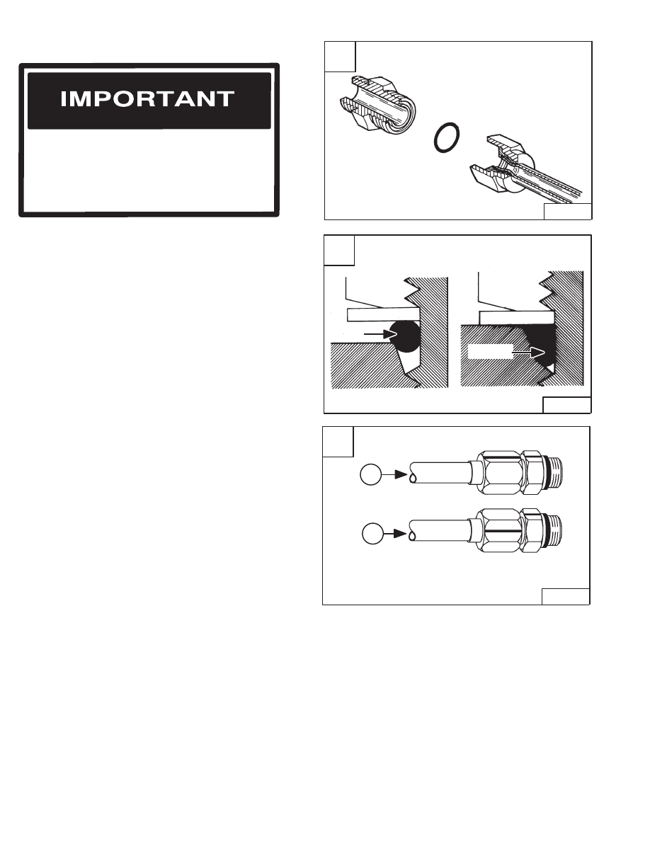
A
B–07575
B
A–01852
Nut
Nut
Washer
Washer
O–ring
O–ring
C
TS–01619
1
2
–9–12–
853, 853H Loader
Service Manual
HYDRAULIC CONNECTION SPECIFICATIONS
O–ring Face Seal Connection
When the fitting is tightened, you can feel when the fitting
is tight to eliminate leakage caused by under or over
torqued fittings. Use vaseline petroleum jelly to hold the
O–ring in position until the fittings are assembled [A].
Straight Thread O–ring Fitting
Lubricate the O–ring before installing the fitting. Loosen the
jam nut and install the fitting. Tighten the jam nut until the
washer is tight against the surface [B].
Tubelines And Hoses
Replace any tubelines that are bent or flattened. They will
restrict flow, which will slow hydraulic action and cause
heat.
Replace hoses which show signs of wear, damage or
weather cracked rubber.
Always use two wrenches when loosening and tightening
hose or tubeline fittings.
Flare Fitting
Use the following procedure to tighten the flare fitting:
Tighten the nut until it makes contact with the seat. Make
a mark across the flats of both the male and female parts
of the connection (Item 1) [C].
Use the chart below to find the correct tightness needed
(Item 2) [C]. If the fitting leaks after tightening, disconnect
it and inspect the seat area for damage.
When repairing hydrostatic and hydraulic
systems, clean the work area before
disassembly and keep all parts clean. Always
use caps and plugs on hoses, tubelines and
ports to keep dirt out. Dirt can quickly damage
the system.
I–2003–0888
Нет комментариевНе стесняйтесь поделиться с нами вашим ценным мнением.
Текст