Loader Bobcat 853, 853H. Service Manual — part 76
BOSS
®
DIAGNOSTIC TOOL
Procedure
The tool listed will be needed to do the following
procedure:
MEL1400 – Diagnostic Tool
Stop the engine.
Lift and block the loader. (See Page 1–1.)
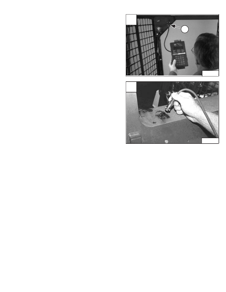
Remove the dust cap from the diagnostic connector plug.
Connect the diagnostic tool plug (Item 1) [A] into the
loader connector.
Use the instructions from the BOSS Operation &
Maintenance Manual to make service checks of BOSS
system operating unit and other components [A].
SENDER AND SENSOR
Service Checks
Use the following information when checking the senders
and sensor with a volt/ohmmeter:
Component
Value
TEMPERATURE SENDER
70 degree F. (21 degree C.)
970 ohms
. . . . . . . . . . . . .
80 degree F. (27 degree C.)
1013 ohms
. . . . . . . . . . . .
ENGINE OIL PRESSURE SENDER
0 PSI
3 ohms Max.
. . . . . . . . . . . . . . . . . . . . . . . . . . . . . .
6 PSI (41 kPa)
7 ohms Min.
. . . . . . . . . . . . . . . . . . . . . . .
50 PSI (345 kPa)
49 ohms
. . . . . . . . . . . . . . . . . . . . . . . .
70 PSI (483 kPa)
59 ohms
. . . . . . . . . . . . . . . . . . . . . . . .
TRANSMISSION CHARGE PRESSURE SENDER
0 PSI
0–5 ohms
. . . . . . . . . . . . . . . . . . . . . . . . . . . . . . . . .
100 PSI (690 kPa)
58 ohms
. . . . . . . . . . . . . . . . . . . . . . .
130 PSI (896 kPa)
75 ohms
. . . . . . . . . . . . . . . . . . . . . . .
150 PSI (1034 kPa)
87 ohms
. . . . . . . . . . . . . . . . . . . . .
FUEL SENDER
Full
30 ohms
. . . . . . . . . . . . . . . . . . . . . . . . . . . . . . . . . . . .
Empty
270 ohms
. . . . . . . . . . . . . . . . . . . . . . . . . . . . . . . .
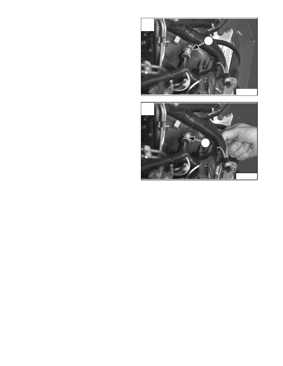
NOTE: Early S/N loaders have the diagnostic plug
located at rear window as shown in Fig. [B].
A
P–03871
1
853,853H Loader
–8–3–
Service Manual
B
CD–09025
RPM SENSOR
Adjustment
Continuity Resistance of 3000–3500 ohms.
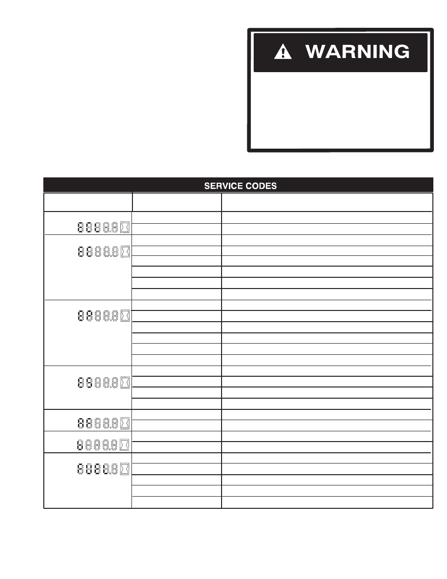
Disconnect the connector [A] from the engine harness.
Loosen the jam nut (Item 1) [A] on the RPM sensor.
Turn the RPM sensor (Item 1) [B] in until it makes contact
with the engine flywheel.
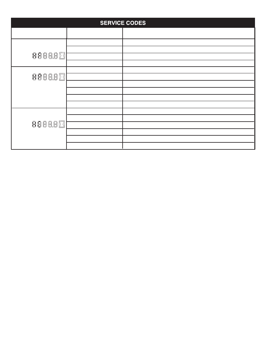
Turn the jam nut until it contacts the flywheel housing. The
jam nut should not be tightened, it needs to turn with the
RPM sensor when the sensor is turned back out for
adjustment.
Turn the RPM sensor and the jam nut out from the
flywheel. Set a clearance of 0.050’’ (1,27 mm) between
the jam nut and the housing with a feeler gauge [B].
Retighten the jam nut.
NOTE: The plastic tip is used as a gauge to set a new
RPM SENSOR. The plastic tip is designed to
come off after the engine is started.
A
P–05193
1
–8–4–
853, 853H Loader
Service Manual
B
P–05192
1
SERVICE CODES
Chart
The following list references the defect codes that are
transmitted to the instrument panel display which can
occur. Some service procedures for correcting the
problems can be found in this manual and other
procedures must be performed ONLY BY QUALIFIED
BOBCAT SERVICE PERSONNEL.
Instructions are necessary before operating or
servicing machine. Read and understand the
Operation & Maintenance Manual, Handbook and
signs (decals) on machine. Follow warnings and
instructions in the manuals when making repairs,
adjustments or servicing. Check for correct
function after adjustments, repairs or service.
Untrained operators and failure to follow
instructions can cause injury or death.
W–2003–0199
SUBJECT
DISPLAY READS
Engine Coolant Level
ECL 1
SHUTDOWN, No Coolant
Engine Coolant Temp.
EC–1.1
SHUTDOWN, Engine Temperature
EC–2.1
WARNING, Engine Temperature
EC 3
Wiring Not Connected
EC 4
Wiring Shorted
EC 5
High Sensor Voltage
EC 7
Sensor Out Of Range
Engine Oil Pressure
EP 1
SHUTDOWN, Pressure
EP 2
WARNING, Pressure
EP 3
Wiring Not Connected
EP 4
Wiring Shorted
EP 5
High Sensor Voltage
EP 7
Sensor Out Of Range
Engine Speed
ES 1
SHUTDOWN, Engine Speed Too High
ES–2.1
WARNING, Engine Speed Slightly High
ES–6
Sensor No Signal
ES–7
Sensor Out Of Range
Air Filter
AF 2
WARNING, Restriction Too High
AF 6
Sensor No Signal
Battery
b–2.1
WARNING, Bad Battery
b–2.2
WARNING, Battery Voltage
Fuel Level
FUEL2
WARNING, Low Level
FUEL3
Wiring Not Connected
FUEL4
Wiring Shorted
FUEL5
High Sensor Voltage
FUEL7
Sensor Out Of Range
CONDITION
853,853H Loader
–8–5–
Service Manual
SUBJECT
DISPLAY READS
Hydrostatic Charge
HF1–2
WARNING, High Restriction
Filter Condition
HF1–6
Sensor No Signal
Hydrostatic Fluid
HP 1
SHUTDOWN, Pressure
HP 2
WARNING, Pressure
HP 3
Wiring Not Connected
HP 4
Wiring Shorted
HP 5
High Sensor Voltage
HP 7
Sensor Out Of Range
Hydrostatic Fluid
HC 1
SHUTDOWN, Temperature
Temperature
HC 2
WARNING, Temperature
HC 3
Wiring Not Connected
HC 4
Wiring Shorted
HC 5
High Sensor Voltage
HC 7
Sensor Out Of Range
CONDITION
–8–6–
853, 853H Loader
Service Manual
Нет комментариевНе стесняйтесь поделиться с нами вашим ценным мнением.
Текст