Loader Bobcat 853, 853H. Service Manual — part 62
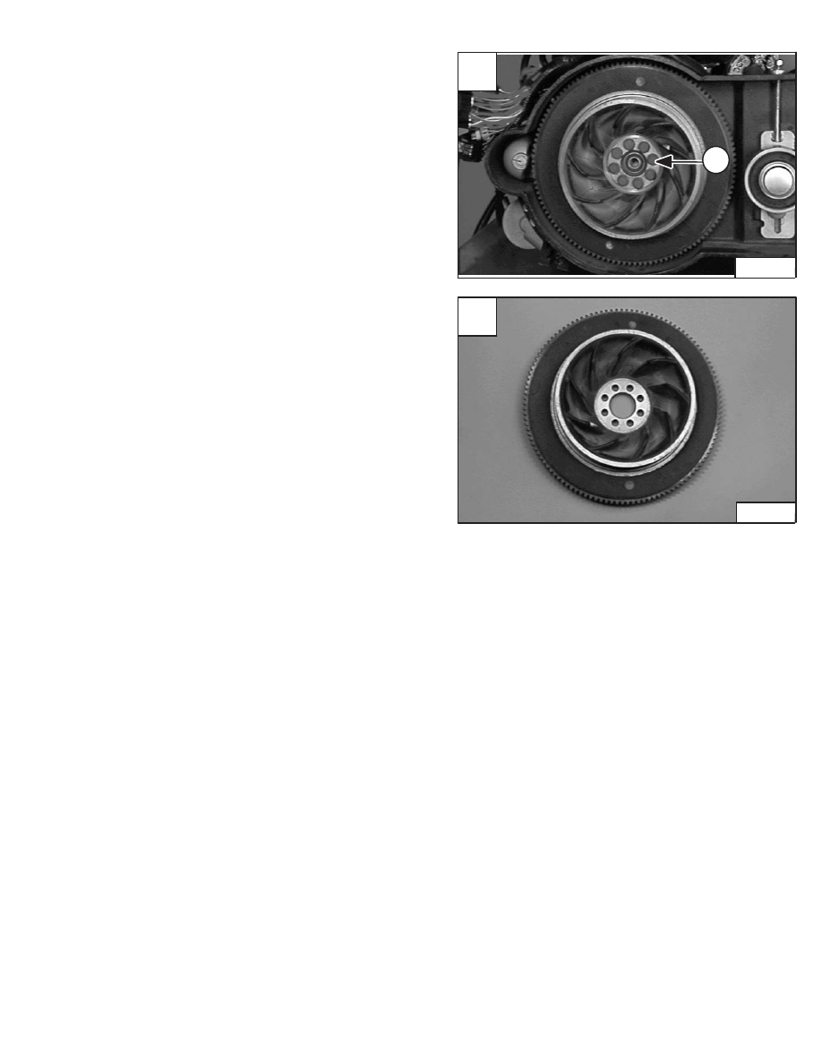
FLYWHEEL
Removal And Installation
Remove the drive belt. (See Page 3–1.)
Remove the bolts (Item 1) [A] from the flywheel.
Installation: Put LOCTITE on the flywheel bolts. Tighten
the bolts to 83–90 ft.–lbs. (113–122 Nm) torque.
Remove the flywheel from the engine crankshaft [B].
Flywheel Ring Gear
The ring gear on the flywheel is an interference fit. Heat
the ring gear enough to expand it and hit it with a hammer
to remove it evenly.
Clean the outer surface of the flywheel to give it a smooth
fit.
Clean the new ring gear and heat it to a temperature of
450–500
°
F (232–260
°
C).
Fit the ring gear over the flywheel. Make sure the gear is
on the seat correctly.
NOTE: Early S/N Loader does not have cooling fins
in flywheel.
A
P–04928
1
853, 853H Loader
–7–37–
Service Manual
B
P–04939
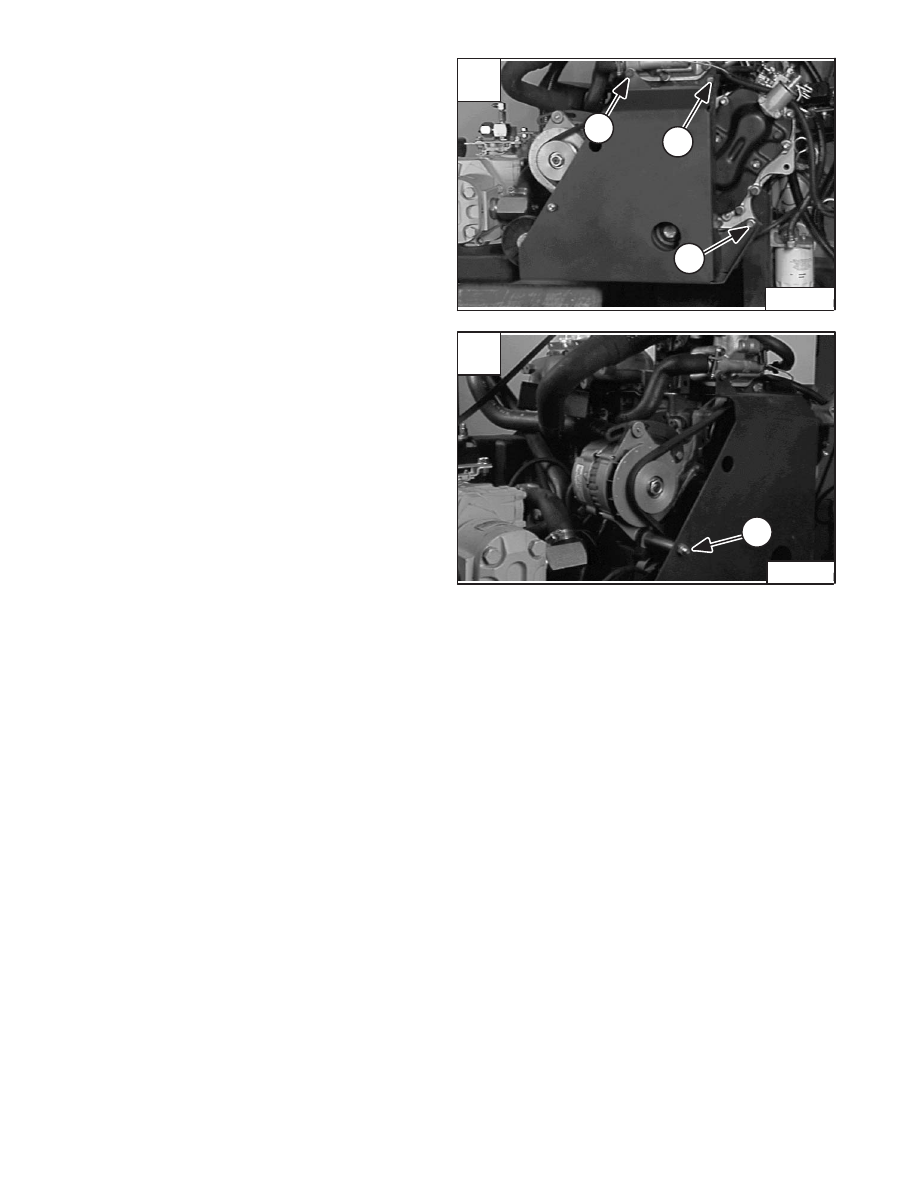
BELT SHIELD
Removal And Installation
Remove the mounting bolt (Item 1) [A] from the
thermostat housing.
Remove the mounting bolt (Item 2) [A] from the cylinder
head.
Remove the mounting bolt (Item 3) [A].
Remove the mounting bolt (Item 1) [B] from the alternator
mounting bracket.
Remove the belt shield from the engine.
A
P–04947
3
2
1
–7–38–
853, 853H Loader
Service Manual
B
P–04945
1
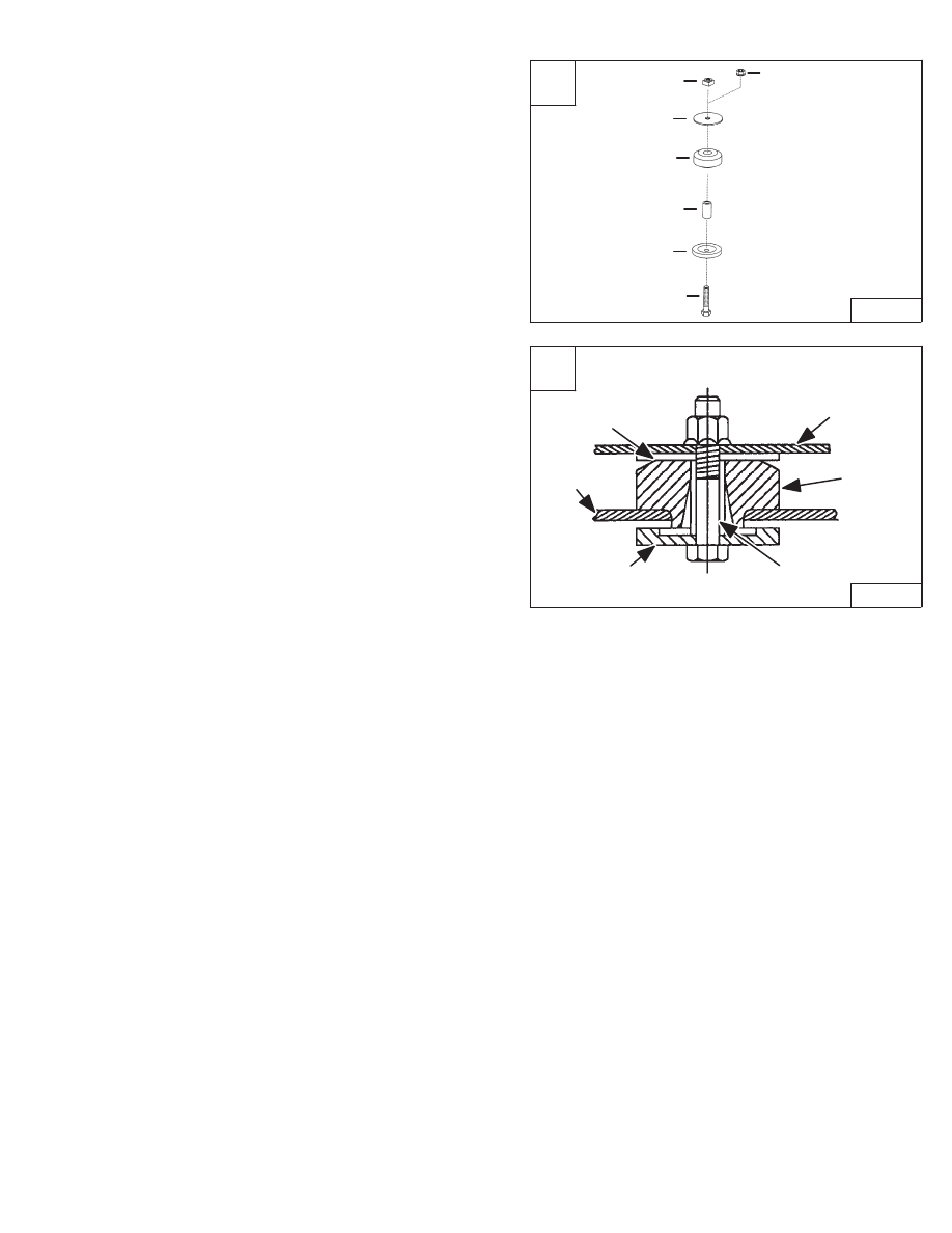
ENGINE MOUNTS
Removal And Installation
There is a kit available to replace the existing engine
mounts in older model 853 loaders.
Use the following procedure to install new engine mounts:
Remove the existing mount from the engine. Refer to
engine Removal And Installation for engine mount
locations.
Replace all four engine mounts (2 front and 2 rear).
Use the parts shown to install the new engine mounts [A].
Item 1 – Square Nut – Used on left side engine mounts
Item 2 – Hex Nut – Used on right side engine mounts
Item 3 – Mount Washer
Item 4 – Engine Mount
Item 5 – Tube Spacer – Front 1.47 inch (37,3 mm)
Rear 1.57 inch (39,9 mm)
Item 6 – Snubbing Washer
Item 7 – Mounting Bolt
Install the new engine mount as shown in the cut away
side view [B].
Tighten the mounting bolts to 90–100 ft.–lbs. (125–130
Nm) torque.
A
MC–01771
2
3
4
6
5
7
1
B
MC–01765
Engine
Mounting
Bracket
Engine
Mount
Spacer
Snubbing
Washer
Washer
Loader
Frame
853, 853H Loader
–7–39–
Service Manual
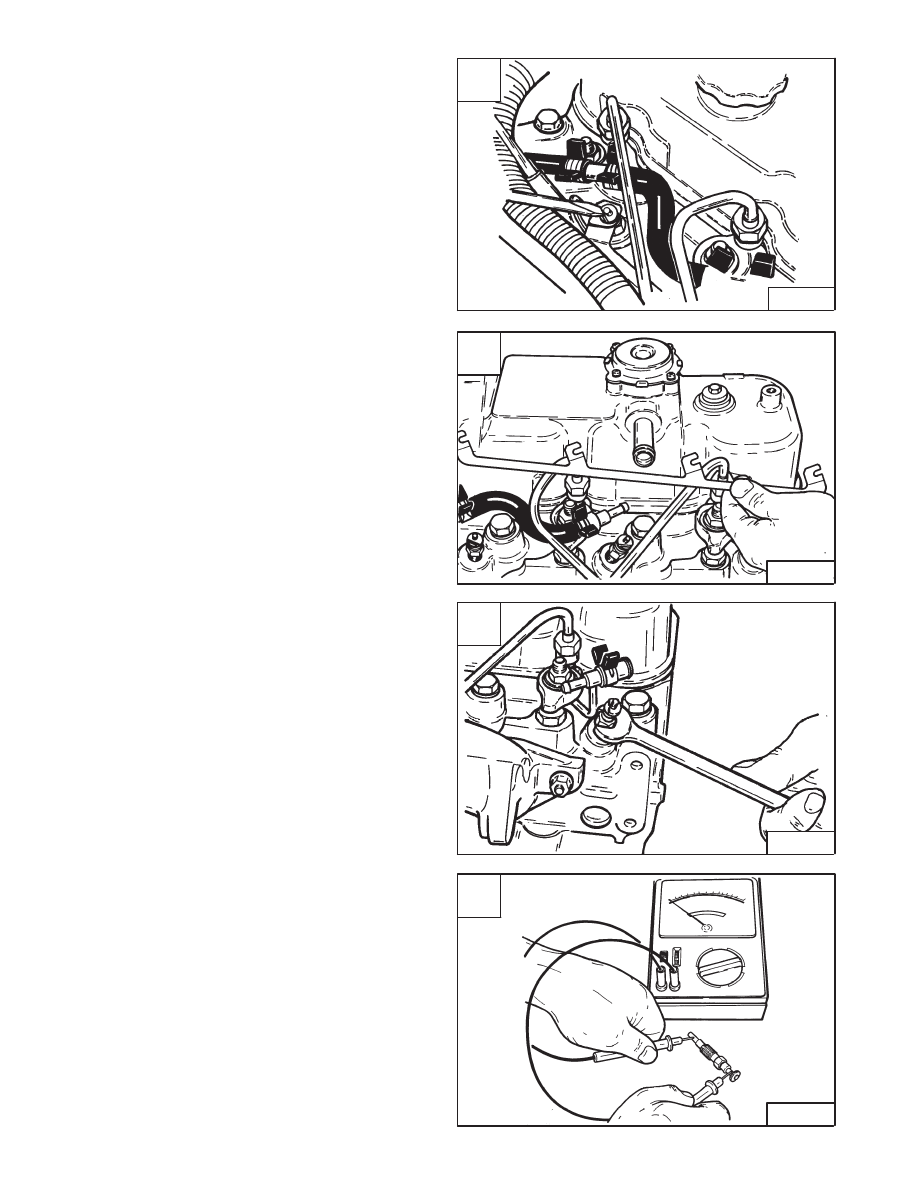
GLOW PLUGS
Removal And Installation
Disconnect the negative (–) cable from the battery.
Remove the electrical bar holddown nuts at the glow
plugs [A].
Remove the electrical connector bar [B].
Remove the glow plug from the cylinder head [C].
Checking The Glow Plugs
Connect the voltmeter to the terminal end of the glow
plug. Touch the other lead from the voltmeter to the
heating end of the glow plug [D].
The reading must be approximately 1.5 ohms. If the
resistance is zero ohms the glow plug has a short circuit.
If the resistance is infinite, the coil of the glow plug is
broken.
A
B–08957
C
B–08923
D
B–11571
–7–40–
853, 853H Loader
Service Manual
B
B–08919
Нет комментариевНе стесняйтесь поделиться с нами вашим ценным мнением.
Текст