Great Wall Pegasus (2006 year). Instruction — part 21
BE-48
Body Electric System
Wiping and Washing System
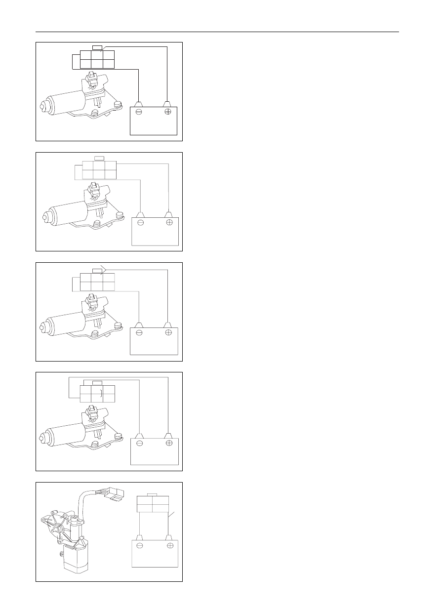
In low-speed operation
Check the front brusher motor
Connect the anode lead to the terminal 2 (1) from accumulator, and
the cathode lead to terminal 3, at this time, the front wiper motor
should be in low-speed operation, otherwise change the front
brusher motor.
In high-speed operation
Connect the anode lead to the terminal 1(2) from the accumulator,
and cathode lead to terminal 3, in such condition, the front wiper
motor should be in high-speed operation.
In case the operation fails to meet the requirement, change the front
wiper motor.
in operation
stop running at the stop position
a.
Run the front wiper motor at low speed and stop it at any
positions excluding the stop position by disconnect the
anode lead from the terminal 2 (1).
b.
Connect the terminals 2 and 5.\
c.
Connect the anode lead to the terminal 6 (4) from the
accumulator, and the cathode lead to terminal 3, check
whether the wiper motor parks at the stop position after
it running for another time, if the requirement is not
satisfied, change the front brusher motor.
Remark: items in parenthesis is for Dr and SF.
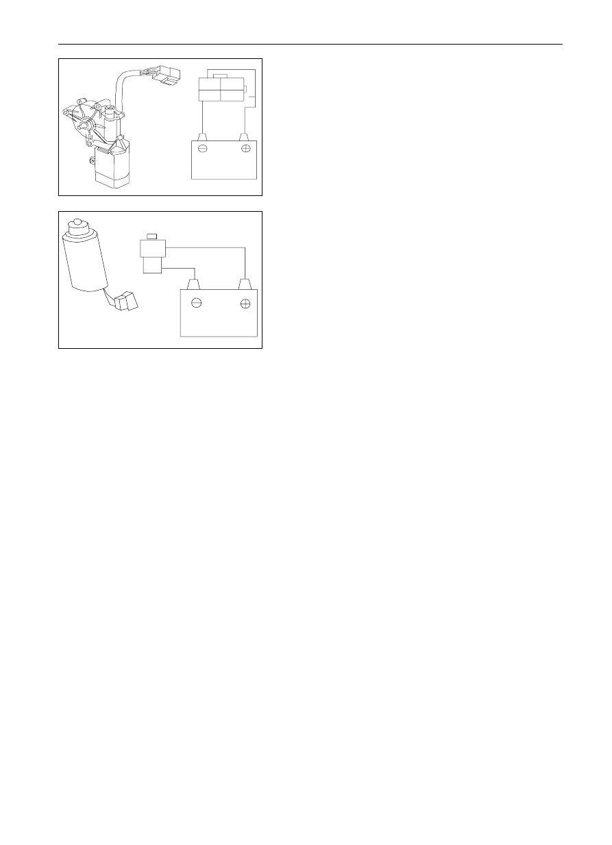
Rear brusher motor inspection
Connect the anode lead to the terminal 3 from the accumulator, and
the cathode lead to terminal 4, at this time, the wiper motor will be
in normal operation, disconnect the terminal 3, the rear wiper motor
should stop running at any position excluding the stop position.
1
2
3
4
1
2
3
4
5
6
1
2
3
4
5
6
1
2
3
4
5
6
1
2
3
4
5
6
-------------------------------------------------------------------------------------------------------------------------------------------------------------
BE-49
Body Electric System
Wiping and Washing System
Connect the anode lead to terminal 3 from the accumulator, and
cathode lead with terminal 4, at this time, the wiper motor should
be in normal operation, under such condition, disconnect the
terminal 3, which is connected with terminal 1, and the anode lead
is connected to the terminal 2, in such case, the rear wiper motor
should stop running at the stop position.
In case the operation fails to satisfy the specified requirement,
change the rear wiper motor.
Inspection on Washer Motor
Connect the anode lead to the terminal 1 from the accumulator, and
the cathode lead to the terminal 2, at this time the washer motor
should be in normal operation.
Notice: this test should be finished rapidly (within 20 seconds).
In case the operation fails to meet the specified requirement, change
the washer motor.
1
2
1
2
3
4
-------------------------------------------------------------------------------------------------------------------------------------------------------------
BE-50
Body Electric System
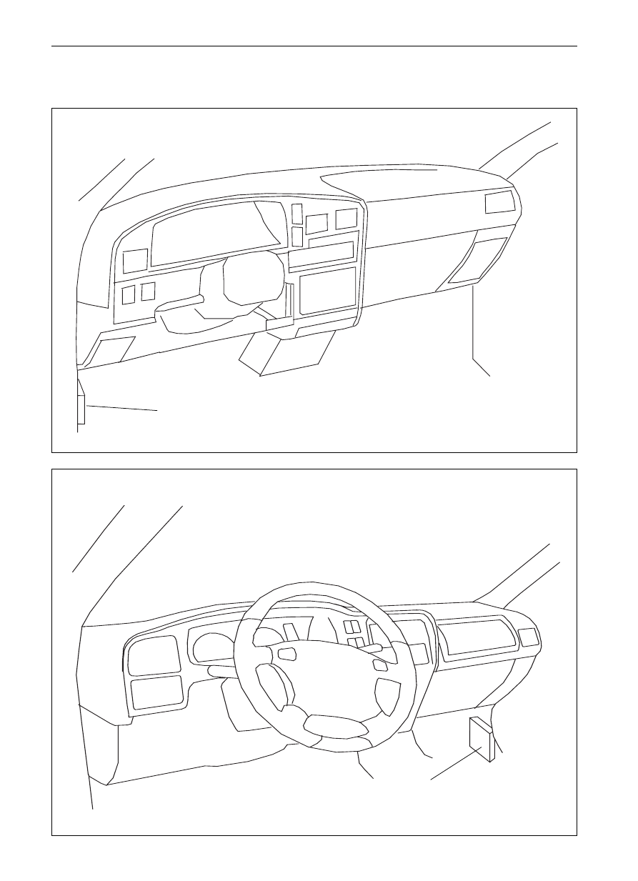
Central Control Lock and Electric Rocker Gear System
Central control lock and electric rocker gear system
Part Mounting position
SL SK SY SJ
Dr SF
Central control lock box
Central control lock box
-------------------------------------------------------------------------------------------------------------------------------------------------------------
BE-51
Body Electric System
Central Control Lock and Electric Rocker Gear System
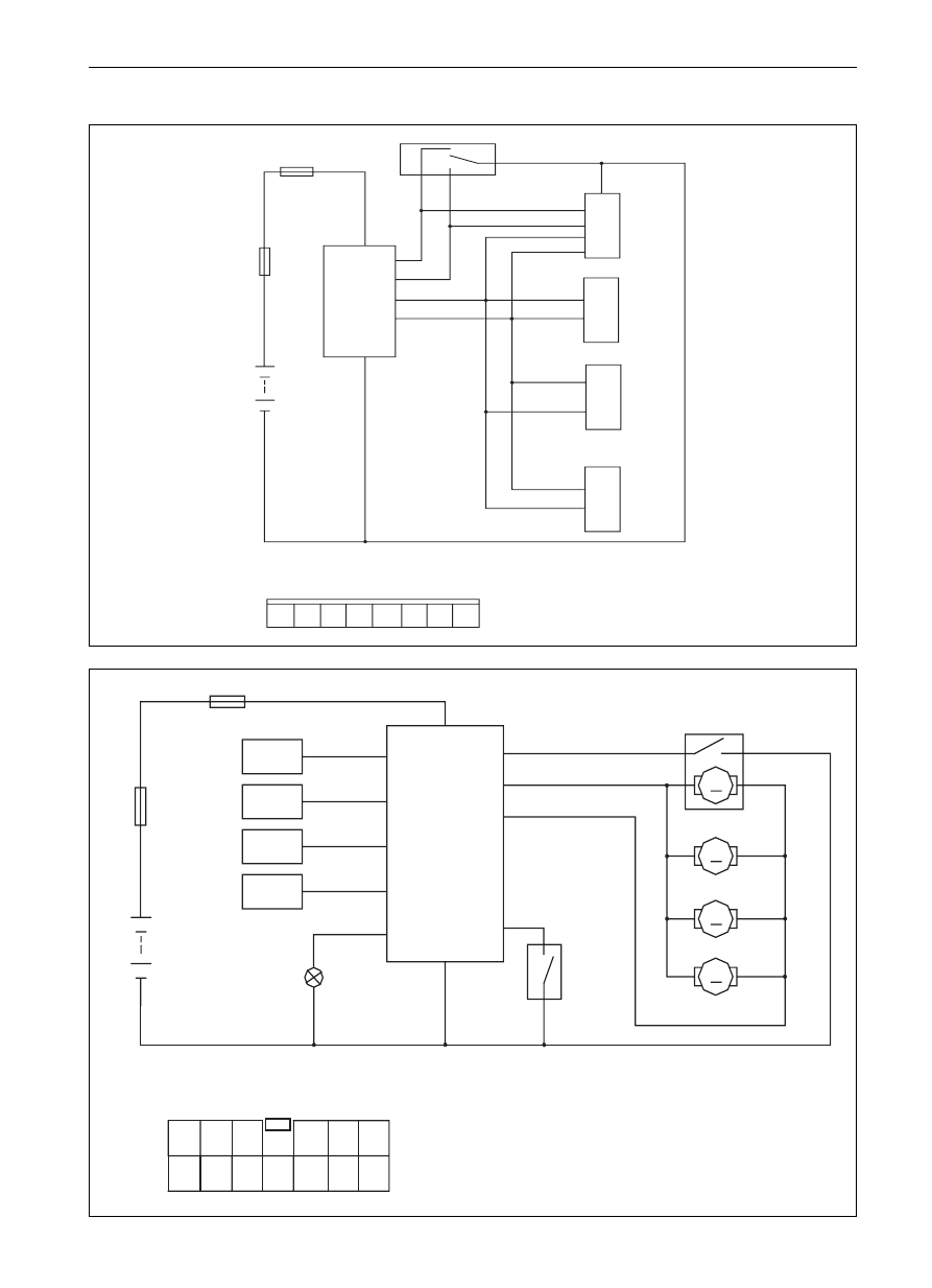
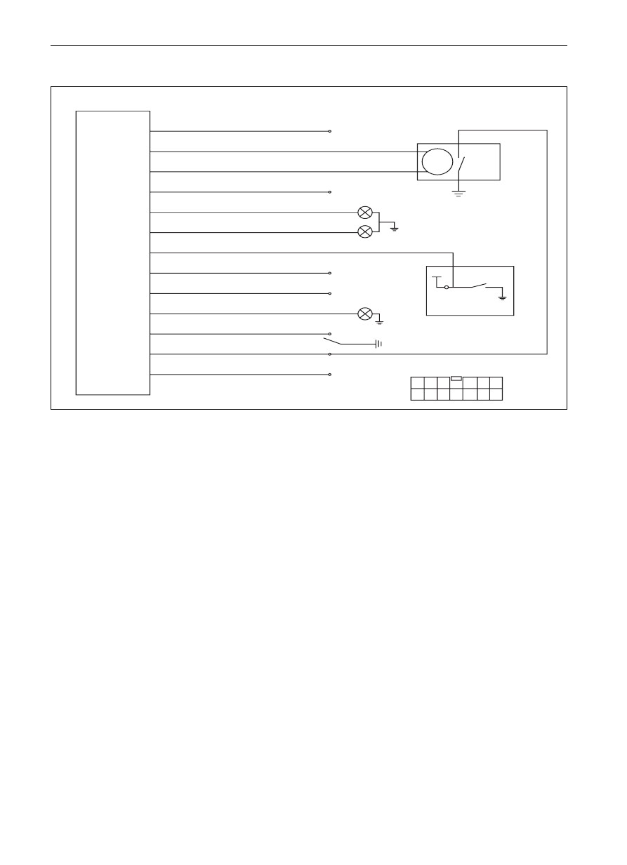
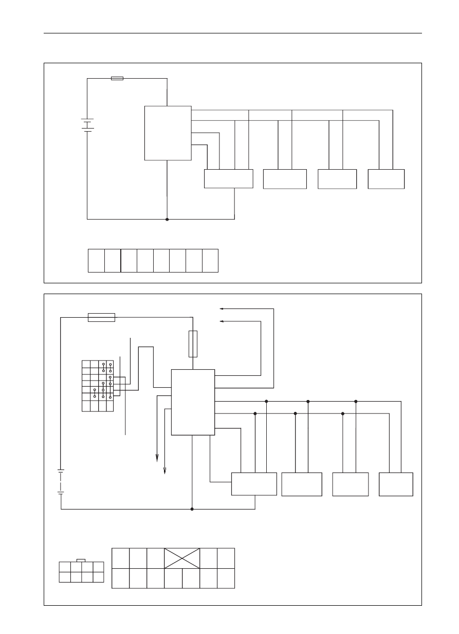
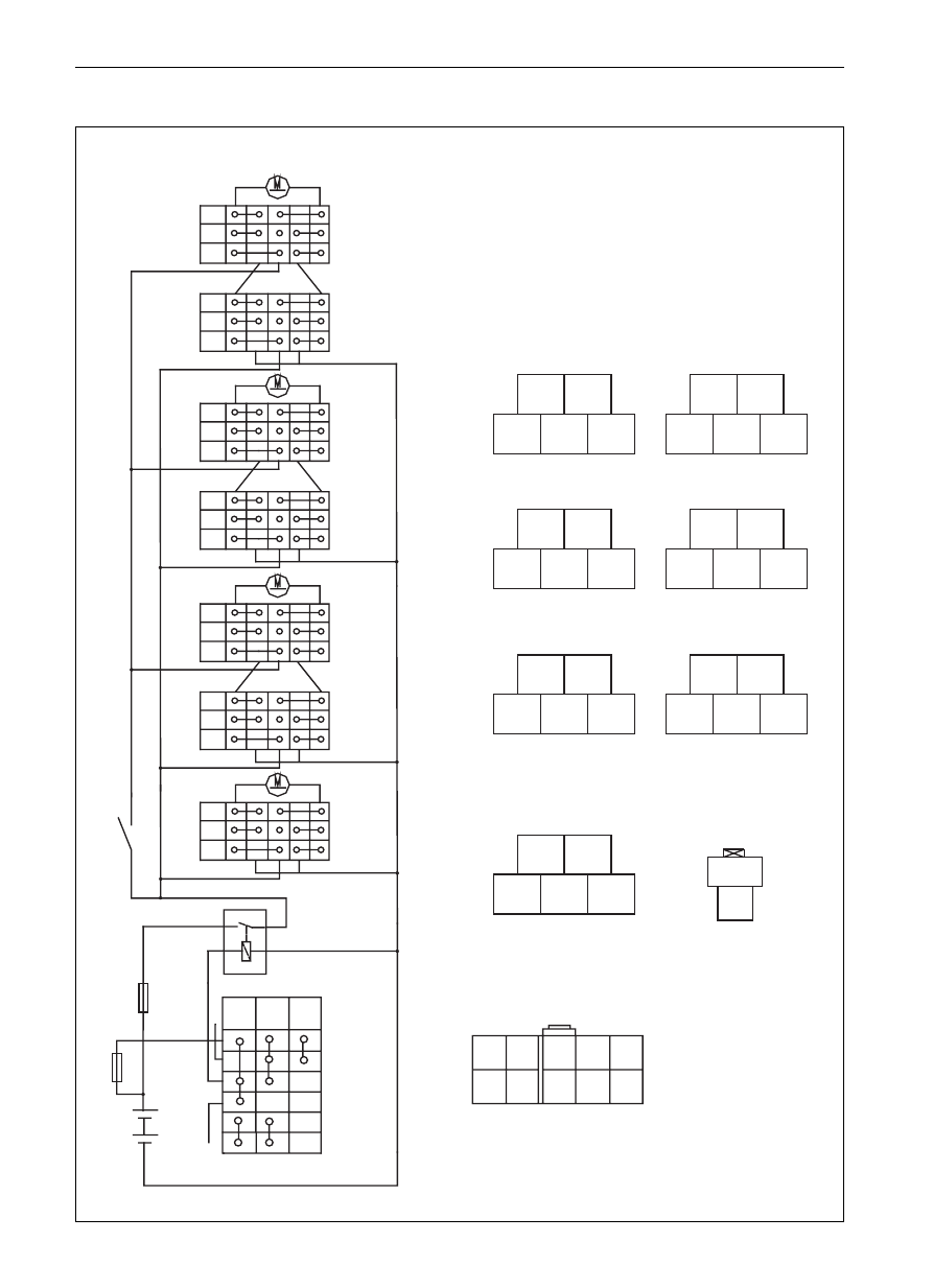
Electric circuit diagram of central control lock
a ê
pc
fuse
2
1
6
5
3
4
left front door switch
left front
main lock
control case of central control lock
1
2
3
4
5
6
7
8
fuse
M
M
M
M
to generator
power lead
to left turn
lamp
to right turn
lamp
to door
lamp switch
control case of central control lock
1
2
3
4
5
6
7
8
9
10
a
12
13
1
6
5
7
10
13
2
3
12
11
central
controller box
battery
lock-head lamp
battery
central controller box
central control lock
switch at left front door
four doors locker
8
right front
main lock
left rear
auxiliary lock
right rear
auxiliary lock
-------------------------------------------------------------------------------------------------------------------------------------------------------------
BE-52
Body Electric System
Central Control Lock and Electric Rocker Gear System
Definition for connecting wire of central control lock
1.
Y/V
Connect the power
to the cell anode on vehicle, in front of which a fuse of 15 A should be set, and
anode of 12V
when the motor is started, the voltage should not less than 10V
2.
B1
Unlocking output of
the locking wire of the CCL actuator, and the grounding wire at the normally
central control lock:
closed contact inside the relay will contact with the normally opening contact at
the common spots inside relay when unlocking with REMOTE CONTROLLER
or instructionly, the wire will output 12 V voltage.
3.
LG
locking signal of
The CCL locking signal is connected to the unlocking wire of actuator of CCL,
central control lock
and the normally closed contact in the interior relay is grounding wire, which will
output 12 V voltage when unlocking with REMOTE CONTROLLER or instructionly
and the common spots of relay contacting the normally opening contact.
4.
non-connection
There is no wire connected at present
5.
G/R
Right turn lamp
Connected to the anode wire of the right turn lamp on the vehicle, and it will output
12 V voltage in operation.
6.
G/Y
Left turn lamp
Connected to the anode wire of left turn lamp on the vehicle, and it will output
12 V voltage when in operation
7.
Br
Negative input of
Which is connected to the door switch and it is grounding when the door is
door switch
opened (the indoor lamp will light)
8.
GD
ON power check cable
Connected to the ON wire of the locking door( there will be 12 v voltage when
rotating the key at
ON position.
9.
Non-connection
This wire is not connected temporarily
10. GD/B Lock head lamp output
There will be 12 V voltage outputted in this wire when opening the door, and will
be powered off (no output) ten seconds later after the door is closed
12. Y/B
Locking signal
Connected to the locking signal wire of CCL at the left front door, and connect
to the grounding wire when in operation.
13. B
Power cathode
Connect to the body (grounding wire) it should be as short as possible, because
the overlong wire will produce the interference source.
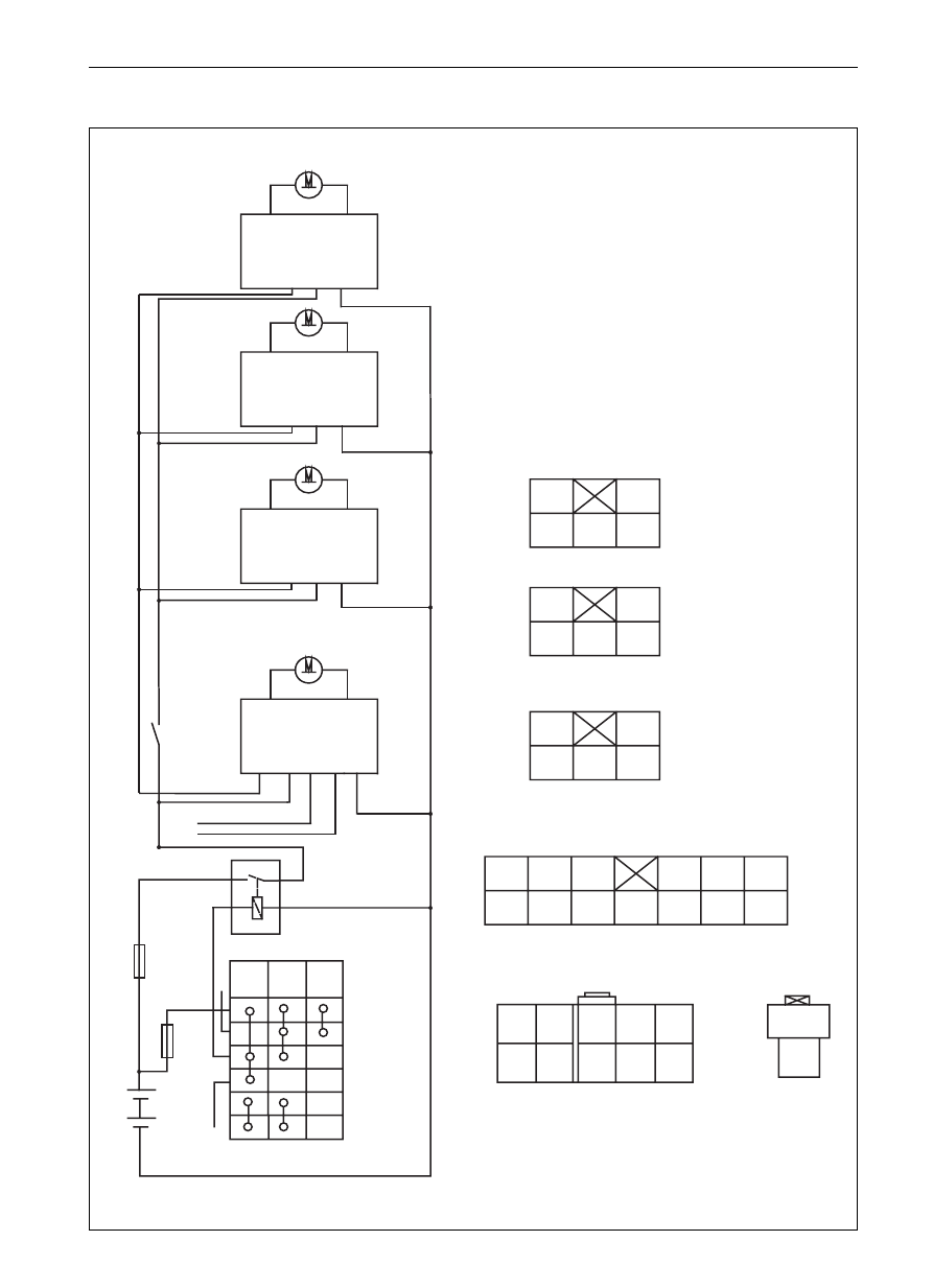
SF
13P
1
2
3
4
5
6
7
8
9
10
11
12
13
Power anode 12 V
unlocking signal of central control lock
locking signal of central control lock
no signal
right turn lamp
left turn lamp
negative input of door switch
ON power check cable
no connection
lock head lamp
unlocking signal
locking signal
power cathode
M
K
Remark: the inner switch in actuator should be
connected when the actuator is in the locking status
Remark: In case the actuator is in locking status,
connect the switch inside.
ON wire connected to key
h
NOs
h
j
left front CCL switch
1
2
3
4
5
6
7
8
9
10
11
12
13
-------------------------------------------------------------------------------------------------------------------------------------------------------------
BE-53
Body Electric System
Central Control Lock and Electric Rocker Gear System
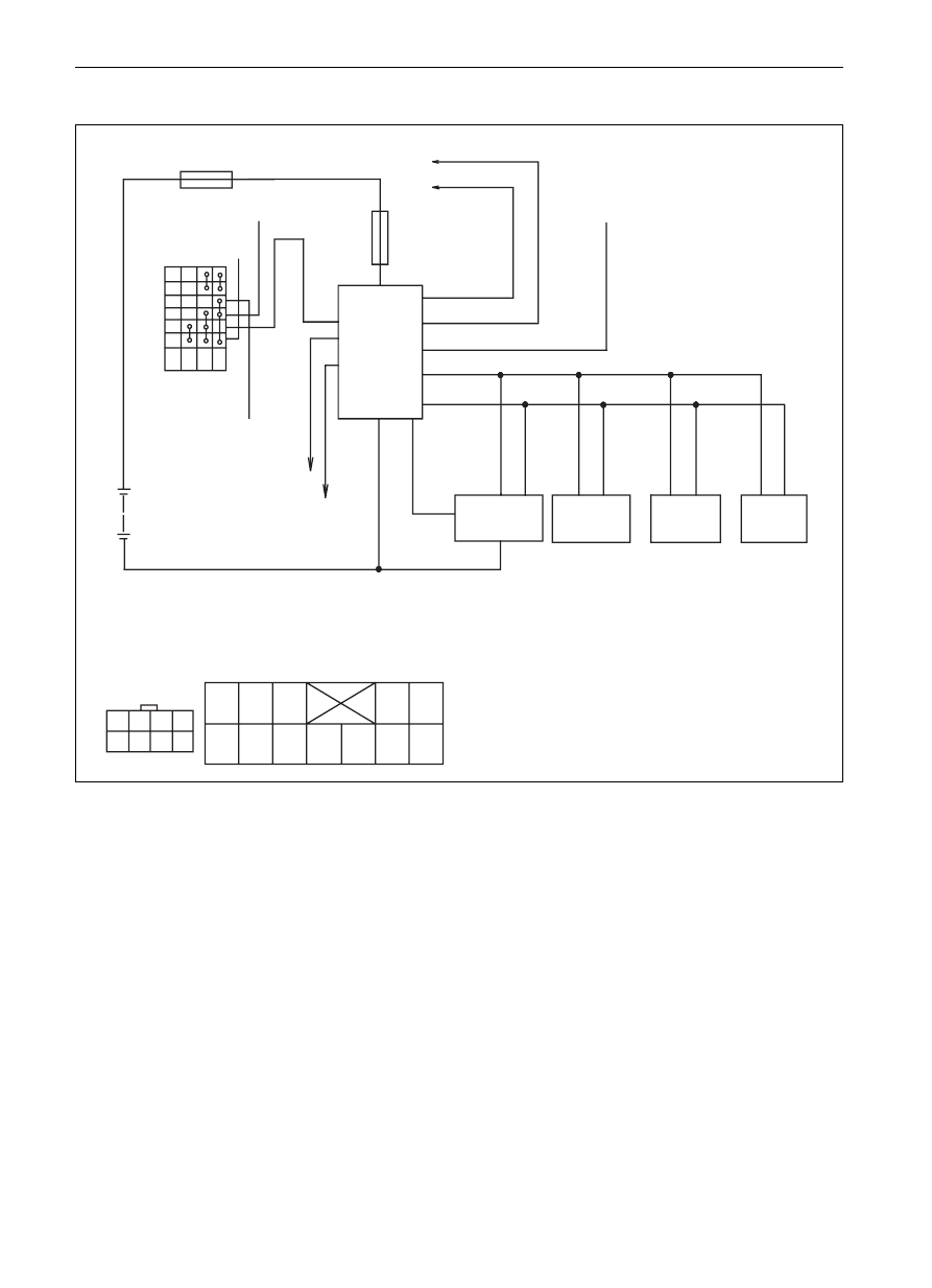
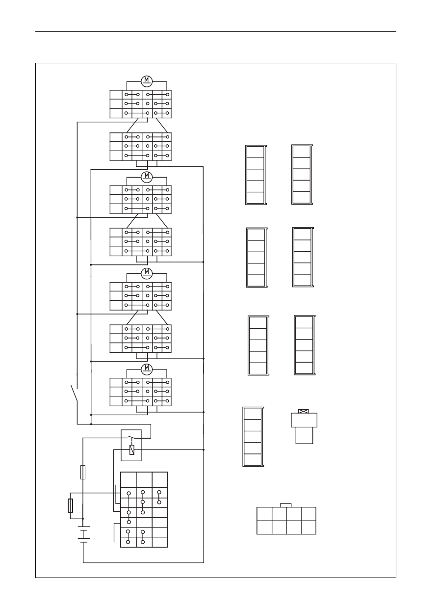
Electric circuit diagram of central control lock (continued)
SL SK
pv
fuse
8
7
6
5
4
3
left front door
main lock
right front door
main lock
left rear door
auxiliary lock
right rear door
auxiliary lock
control case of central control lock
1
2
3
4
5
6
7
8
fuse
ignition switch
ACC ON ST
1
11
10
8
9
1
6
4
5
3
7
12
left front main
lock
right front
main lock
left rear
auxiliary lock
right rear
auxiliary lock
ignition switch
control case of central control lock
1
2
3
4
5
6
7
8
1
2
3
4
5
6
7
8
9
10
11
12
battery
door lamp switch
speed sensor
central
controller box
turn lamp
battery
central
controller box
-------------------------------------------------------------------------------------------------------------------------------------------------------------
BE-54
Body Electric System
CCL and Electric Rocker Gear System
Electric circuit diagram of CCL
SJ Top-grade SY
fuse
ACC ON ST
N
ignition switch
11
10
8
9
12
7
4
5
2
6
1
left front main lock
right front main
lock
left rear auxiliary
lock
right rear auxiliary
lock
ignition switch
1
2
3
4
5
6
7
8
1
2
3
4
5
6
7
8
9
10
11
12
battery
central controller
box
speed sensor
turn lamp
left front electric rocker gear switch
central controller box
door lamp switch
-------------------------------------------------------------------------------------------------------------------------------------------------------------
BE-55
Body Electric System
CCL and Electric Rocker Gear System
Definition of the connecting wire of CCL
1. G/R (G/W) Turn lamp
Connected to the anode wire of the turn lamp (right ) on vehicle, it will output 12 V voltage
when it is in operation
2. O
w/b1) Window-shutting signal output
This wire has one second of voltage output of 12V when the car door is locking. (top SY SJ)
3. No connection
4. G (Y) Unlocking output of CCL
Connected to the locking wire of actuator of CCL, and the normally closed contact in the
internal relay is the grounding wire.It will output 12 v voltage when locking with REMOTE
CONTROLLER or instructionly because the common spot of relay will contact the normally
opening contact.
5. Bl (G) Locking output of CCL
Connected to the locking wire of actuator of CCL, and the normally closed contact inside
the internal relay is the grounding wire.It will output 12 V voltage when locking with
REMOTE CONTROLLER or instructionly because the common sots of relay will contact
with the normally opening contact.
6. Gr (G/B) Turn lamp
Connected to the anode wire of left turn lamp of vehicle, it will output 12 v Voltage when in
operation.
7. W (W) Instructionly controlled unlocking signal
The door lock control the locking process through the instruction unlocking switch at left front
door, that is, under the locking condition, press the switch, the lock will be opened (the
switch will return to the connection situation automatically after pressing.
8. Br (R/B) Negative output of door switch
Connected to the car door lamp switch, it is connected to the grounding wire (the indoor
lamp will light when opening the door.
9. R/G (G/B) Rotating speed test
The car door will lock automatically when the vehicle reaches a certain speed.
10. W(R )
ACC test
Connect to the ACC wire, which will have 12 V voltage when the key is rotated to the ACC position.
11. R (R )
Power anode (12V)
Connect to the anode of accumulator on vehicle, in front of which should be set the fuse
so that the voltage will be no less than 10V when the starter is in operation.
12. B(B) Power cathode
Connect to the body (grounding wire), it should be short as possible as can because the
overlong wire will produce the interference source.
SY SJ
1
2
3
4
5
6
7
8
9
10
11
12
left turning light
instruction switch locking signal
closing window output
none
door switch negative input
speed test
ACC test
power anode 12V
remote control opening lock output
power cathode
remote control closing lock output
12V
W
K
door switch
K
M
M
M
M
Items in the parenthesis is for SY diesel model
Items with
are configuration for SJ and top SY
-------------------------------------------------------------------------------------------------------------------------------------------------------------
BE-56
Body Electric System
CCL and Electric Rocker Gear System
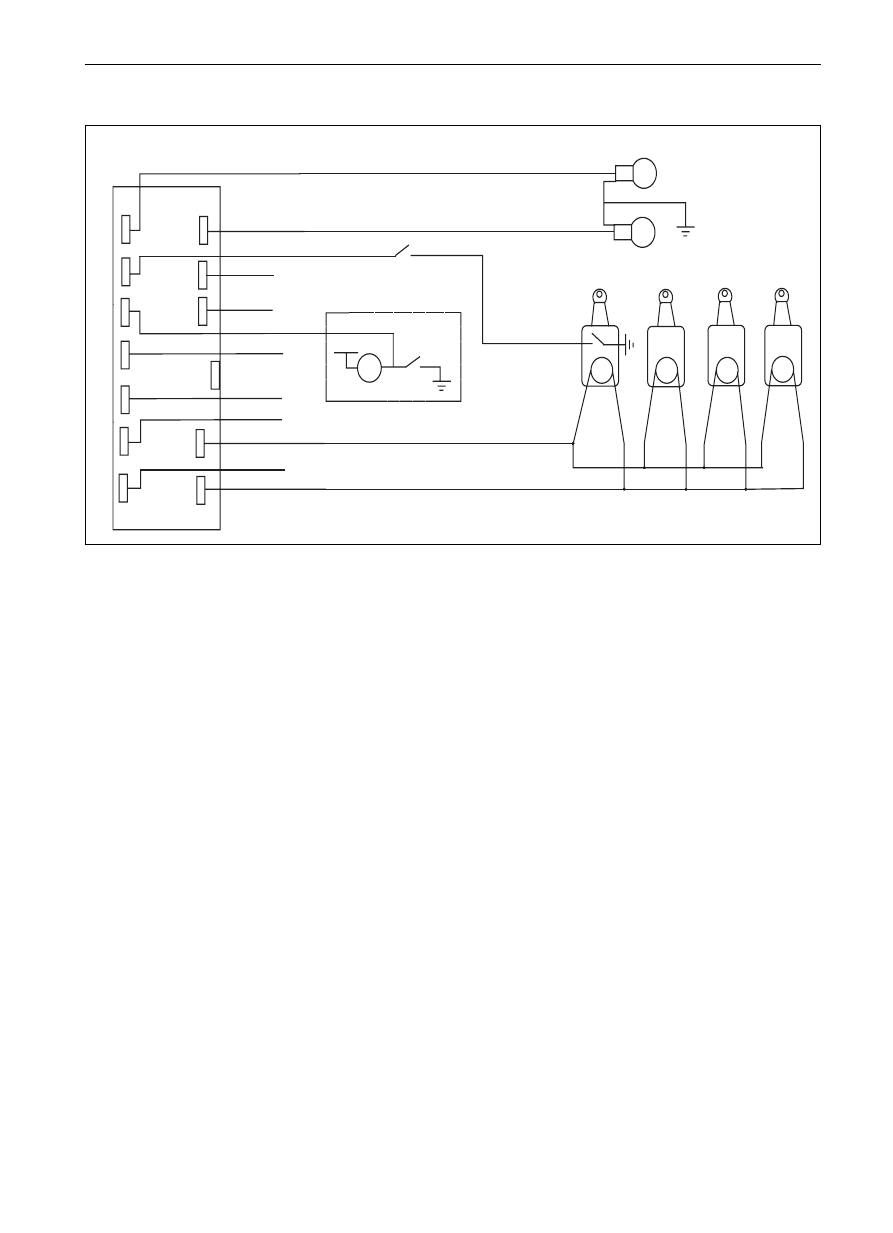
Diagram of electric rocker gear
Dr
main
auxiliary
1
2
3
4
5
1
2
3
4
5
1
2
3
4
5
1
2
3
4
5
main
auxiliary
main
auxiliary
1
2
3
4
5
1
2
3
4
5
1
2
3
4
5
1
2
1
2
3
4
5
6
7
8
9
10
1
2
1
2
4
3
5
2
1
3
4
5
1
2
2
1
3
4
R
N
2
3
4
5
2
1
2
1
3
4
5
2
1
3
4
5
1
2
1
2
3
4
5
electric window relay
ST
ON ACC
auxiliary
falling
stop
raising
main
falling
stop
raising
auxiliary
main
falling
stop
raising
falling
stop
raising
auxiliary
main
falling
raising
falling
stop
raising
right rear
left rear
right front
left
front
inhibitor switch
falling
stop
raising
stop
right front door switch
left front door switch
battery
fuse
ignition switch
ignition switch
electric rocker gear
left rear door switch
left rear door switch
-------------------------------------------------------------------------------------------------------------------------------------------------------------
BE-57
Body Electric System
CCL and Electric Rocker Gear System
SF
right rear door switch
1
2
3
4
5
left rear door switch
1
2
3
4
5
right front door switch
1
2
3
4
5
left front door switch
1
2
3
4
5
6
7
8
9
10
11
12
13
ignition switch
1
2
3
4
5
6
7
U
9
10
electric rocker gear
1
2
2
1
5
2
3
1
4
2
1
2
5
1
4
3
1
2
5
2
1
4
3
2
1
12
7
13
1
3
4
2
electric window relay
ST
ON
ACC
battery
fuse
ignition switch
right rear
left rear
right
front
left
front
control lock
12
11
inhibitor switch
Diagram of electric rocker gear
-------------------------------------------------------------------------------------------------------------------------------------------------------------
BE-58
Body Electric System
CCL and Electric Rocker Gear System
Diagram of electric rocker gear
SL SK SY
5
2
1
1
2
3
4
ST
ON ACC
N
O
P
Q
R
S
T
U
1
2
1
2
3
4
5
1
2
3
4
5
1
2
3
4
5
1
2
3
4
5
1
2
3
4
5
1
2
5
right rear
auxiliary
falling
stop
raising
main
falling
stop
raising
auxiliary
main
falling
stop
raising
falling
stop
raising
auxiliary
main
falling
raising
falling
stop
raising
inhibitor switch
falling
stop
raising
stop
battery
fuse
main
auxiliary
main
auxiliary
main
auxiliary
electric window relay
left rear
right front
left front
right front door switch
left front door switch
ignition switch
electric rocker gear
left rear door switch
ignition switch
N
2
3
4
5
4
3
left rear door switch
1
2
1
5
1
2
3
4
5
3
2
4
1
2
1
5
1
2
3
4
5
3
2
4
1
2
1
5
1
2
3
4
5
3
2
4
-------------------------------------------------------------------------------------------------------------------------------------------------------------
BE-59
Diagram of electric rocker gear
SJ Top-grade SY
2
1
4
3
5
1
6 2
6
1
5
2
1
4
3
2
1
Q
6
1
5
3
2
1
5
Q
6
1
10
central control lock
left front
right front
left rear
right rear
1
2
1
2
3
4
5
6
1
2
3
4
5
6
1
2
3
4
5
6
1
2
3
4
5
6
7
8
9
10
fuse
battery
iocking switch
8
3
ACC
ON
ST
ignition switch
electric rocker gear
right rear door switch
left rear door switch
right front door switch
left front door switch
Body Electric System
CCL and Electric Rocker Gear System
-------------------------------------------------------------------------------------------------------------------------------------------------------------

BE-60
Inspection on Common Trouble
Trouble
Possible causes
Repairing approaches
Burned out fuse
Change and check whether there is
short circuit
Wiring failure
Seize-up of electric rocker gear
or mechanical lock
Failure of brush-rocker or lock
out device
Make reparation as required.
Make reparation as required.
Change
The indicating lamp of electric rocker gear
switch doesn
t work
Wiring failure
Failure of indicating lamp locates
interior side of switch
Make reparation as required.
Change
There is no electricity in the
Change the cell
remote controller
Both remote controller cannot
control the CCL
Glass cannot raise automatically after the
car door is locked (top SY SJ)
Wiring failure
Failure of Control case of CCL
Brush-rocker switch failure
Make reparation as required.
Change
Change
Body Electric System
CCL and Electric rocker Gear System
Electric rocker gears at four
doors don
t work
The CCL at four doors don
t work
Burned out fuse
Change and check whether there is
short circuit
The electric rocker gear or
CCL at one
door doesn
t work
One remote controller cannot c
ontrol the CCL
Controller box damage
Change
-------------------------------------------------------------------------------------------------------------------------------------------------------------
BE-61
Acoustical equipment system
The devices in this series is the vehicle-equipped acoustical receiver and recorder whose function is realized through
the electronic tuner and CD recorder, therefore, it can receive the amplitude modulation, frequency modulation and
stereo broadcast and can record the CD disc, what??s more, it is with the advanced electric anti-quaking, strong capability
of error correction, fashionable blue LCD liquid crystal digital display, and four-way power output. The device in this
series also has the characteristics such as low distortion, large output power and good performance of anti-interference,
broad frequency range and sweet sound, etc.
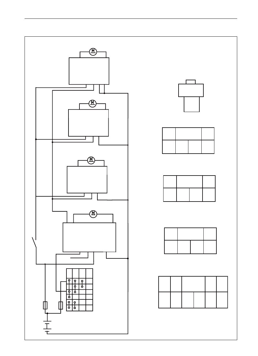
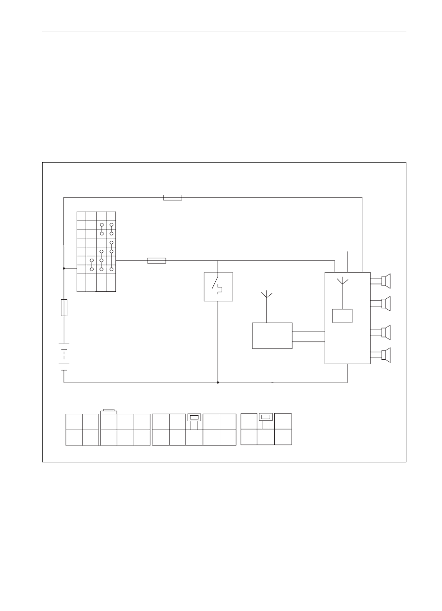
Diagram of Acoustical equipment system
SF
fuse
ignition switch
ACC ON
ST
side-window aerial
CD device
loudspeaker
ignition switch
CD plugging element
plugging elements of rear
loudspeaker of CD device
1
2
3
4
5
6
7
8
9
10
1
2
3
4
5
6
7
8
9
1
2
3
4
5
5
4
1
2
3
5
3
8
4
9
7
5
6
1
7
Note: For Dr the antenna is the rod type.
battery
cigarette lighter
left front
right front
left rear
right rear
from small lamp relay
2
amplifier
Body Electric System
Acoustical Equipment System
-------------------------------------------------------------------------------------------------------------------------------------------------------------
BE-62
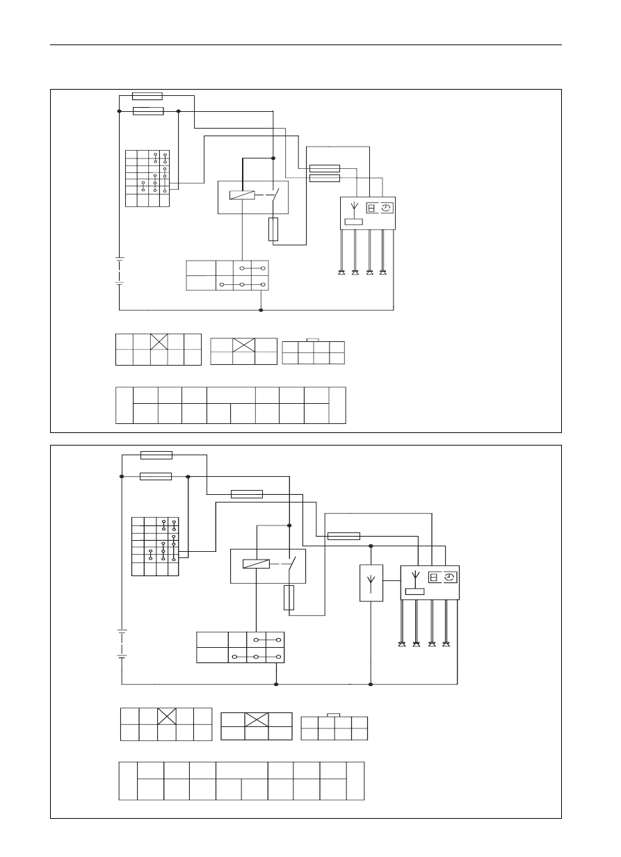
Diagram of acoustical equipment system (continued)
SL SK
SY SJ
fuse
ignition switch
ACC ON ST
4
1
small lamp
large lamp
6
6
2
5
9 P Q 8 1 3 O 5 7
receiver
receiver
1
2
3
4
5
6
7
8
9
1
2
3
4
5
4
3
2
1
5
6
7
8
ignition switch
combined switch
8
7
6
5
16
15
14
NP
12
11
4
3
2
1
9
10
fuse
ignition switch
ACC ON ST
4
1
small lamp
large lamp
6
1
6
2
5
9 3 4 8 1 3 2 5 7
CD device
CD device
1
2
3
4
5
6
7
U
9
1
2
3
4
5
ignition switch
4
3
2
1
R
6
8
combined switch
8
7
6
5
16
NR
14
13
12
11
10
9
2
3
4
N
receiver
small lamp relay
small lamp relay
electric aerial
CD device
battery
battery
fuse
fuse
7
Body Electric System
Acoustical Equipment System
-------------------------------------------------------------------------------------------------------------------------------------------------------------

BE-63
Trouble
Possible causes
Repairing approaches
Page
Receiver
CD recorder
Lack of power supply
Burned out fuse
Wiring failure
Change the fuse and check whether there is
short circuit;
Make reparation as required
Loudspeaker doesn
t work Faalure of loudspeaker
Wiring failure
Chaange the loudspeaker;
Make reparation as required.
Do not read the tape or disc
Receiver failure or
Change the receiver or CD recorder
CD recorder failure
AM or FM doesn
t work
Receiver or CD recorder failure
Change the receiver or CD recorder
VCD
Non-opening of devices
Aerial failure
Wiring failure
Main machine failure
Change or repair it as required;
Make reparation as required.
Change the main device
Neither image nor sound is
broadcasted
Failure of main device;
converter box failure plus disc box
failure
Make inspection as required and change
the parts with failure
No image when backing up
Wiring failure
Failure of video camera
Conduct an inspection as required and
change the parts with failure
FM/TV failure
Failure of aerial amplifier
Weak signal from TV station
Make an inspection as required and change
the parts with failure
Screen cannot be turned over Unsuitable main device adjustment
Failure of main device
Adjust according to the application
instruction;change the main device
Disc box cannot be pushed
Failure of disc box
Make an inspection as required
outside
Bass speaker doesn
t work Wiring failure
Failure of bass speaker
Make reparation as required.
Change the bass speaker.
Electric
aerial
Non-raising when receiver is
opened
Wiring failure
Failure of electric aerial
Make reparation as required.
Change the electric aerial
Falling seize-up
Wiring failure
Failure of electric aerial.
Make an inspection as required and change
the parts with failure.
BE-64
BE-64
BE-64
BE-65
BE-65
Inspection on Common Trouble
Body Electric System
Acoustical Equipment System
-------------------------------------------------------------------------------------------------------------------------------------------------------------
Нет комментариевНе стесняйтесь поделиться с нами вашим ценным мнением.
Текст