Toyota FJ Cruiser (GSJ 10, 15 series). Manual — part 89

1GR-FE ENGINE CONTROL SYSTEM – SFI SYSTEM
ES–311
ES
(f)
Select the following menu items: DIAGNOSIS /
ENHANCED OBD II / DTC INFO / CURRENT CODES.
(g) Read DTCs.
Result
B
A
Display (DTC Output)
Proceed To
P2121
A
No output
B
SYSTEM OK
REPLACE ECM (See page
)
ES–312
1GR-FE ENGINE CONTROL SYSTEM – SFI SYSTEM
ES
HINT:
•
Although the DTC titles say oxygen sensor, these DTCs relate to the Air-Fuel Ratio (A/F) sensor.
•
Sensor 1 refers to the sensor mounted in front of the Three-Way Catalytic Converter (TWC) and
located near the engine assembly.
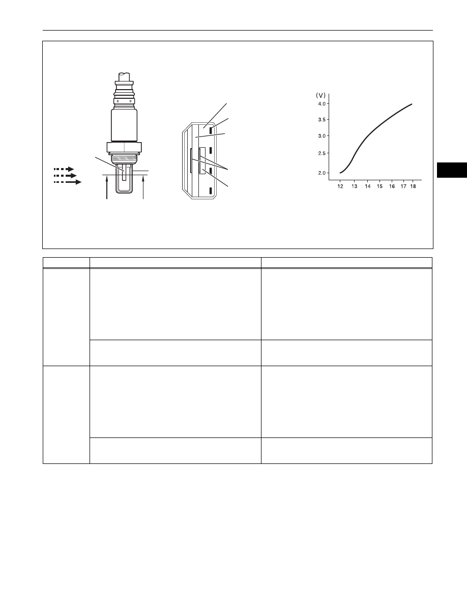
DESCRIPTION
The A/F sensor generates a voltage
*
that corresponds to the actual air-fuel ratio. This sensor voltage is
used to provide the ECM with feedback so that it can control the air-fuel ratio. The ECM determines the
deviation from the stoichiometric air-fuel ratio level, and regulates the fuel injection time. If the A/F sensor
malfunctions, the ECM is unable to control the air-fuel ratio accurately.
The A/F sensor is the planar type and is integrated with the heater, which heats the solid electrolyte
(zirconia element). This heater is controlled by the ECM. When the intake air volume is low (the exhaust
gas temperature is low), a current flows into the heater to heat the sensor, in order to facilitate accurate
oxygen concentration detection. In addition, the sensor and heater portions are narrower than the
conventional type. The heat generated by the heater is conducted to the solid electrolyte though the
alumina, therefore the sensor activation is accelerated.
In order to obtain a high purification rate of the carbon monoxide (CO), hydrocarbon (HC) and nitrogen
oxide (NOx) components in the exhaust gas, a TWC is used. For the most efficient use of the TWC, the
air-fuel ratio must be precisely controlled so that it is always close to the stoichiometric level.
*
: Value changes inside the ECM. Since the A/F sensor is the current output element, a current is
converted in to a voltage inside the ECM. Any measurements taken at the A/F sensor or ECM connectors
will show a constant voltage.
DTC
P2195
Oxygen (A/F) Sensor Signal Stuck Lean (Bank 1
Sensor 1)
DTC
P2196
Oxygen (A/F) Sensor Signal Stuck Rich (Bank 1
Sensor 1)
DTC
P2197
Oxygen (A/F) Sensor Signal Stuck Lean (Bank 2
Sensor 1)
DTC
P2198
Oxygen (A/F) Sensor Signal Stuck Rich (Bank 2
Sensor 1)
1GR-FE ENGINE CONTROL SYSTEM – SFI SYSTEM
ES–313
ES
HINT:
•
DTCs P2195 and P2196 indicate malfunctions related to bank 1 A/F sensor circuit.
•
DTCs P2197 and P2198 indicate malfunctions related to bank 2 A/F sensor circuit.
•
Bank 1 refers to the bank that includes cylinder No. 1.
•
Bank 2 refers to the bank that includes cylinder No. 2.
•
When any of these DTCs are set, check the A/F sensor voltage output by selecting the following menu
items on an intelligent tester: DIAGNOSIS / ENHANCED OBD II / DATA LIST / PRIMARY / AFS B1S1
or AFS B2S1.
•
Short-term fuel trim values can also be read using an intelligent tester.
DTC No.
DTC Detection Conditions
Trouble Areas
P2195
P2197
Conditions (a) and (b) continue for 10 seconds or more (2 trip
detection logic)
(a) Air-Fuel Ratio (A/F) sensor voltage more than 3.8 V
(b) Heated Oxygen (HO2) sensor voltage 0.15 V or more
•
Open or short in A/F sensor (bank 1, 2 sensor 1) circuit
•
A/F sensor (bank 1, 2 sensor 1)
•
A/F sensor (bank 1, 2 sensor 1) heater
•
A/F sensor heater relay
•
A/F sensor heater and relay circuits
•
Air induction system
•
Fuel pressure
•
Injector
•
ECM
While fuel-cut operation performed (during vehicle
deceleration), air-furl ratio (A/F) sensor current 3.6 mA or
more for 3 seconds (2 trip detection logic)
•
A/F sensor
•
ECM
P2196
P2198
Conditions (a) and (b) continue for 10 seconds or more (2 trip
detection logic)
(a) A/F sensor voltage less than 2.8 V
(b) HO2 sensor voltage less than 0.6 V
•
Open or short in A/F sensor (bank 1, 2 sensor 1) circuit
•
A/F sensor (bank 1, 2 sensor 1)
•
A/F sensor (bank 1, 2 sensor 1) heater
•
A/F sensor heater relay
•
A/F sensor heater and relay circuits
•
Air induction system
•
Fuel pressure
•
Injector
•
ECM
While fuel-cut operation performed (during vehicle
deceleration), air-furl ratio (A/F) sensor current less than 1.4
mA for 3 seconds (2 trip detection logic)
•
A/F sensor
•
ECM
A
A
Element
Exhaust Gas
A-A Section
Platinum Electrode
Cover
Atmospheric Air
Heater
Alumina
Solid Electrolyte
(Zirconia Element)
Air Fuel Ratio
A/F Sensor Voltage
ECM Monitored
A107164E08
ES–314
1GR-FE ENGINE CONTROL SYSTEM – SFI SYSTEM
ES
•
The ECM regulates the voltages at the A1A+, A2A+, A1A- and A2A- terminals of the ECM to a
constant level. Therefore, the A/F sensor voltage output cannot be confirmed without using an
intelligent tester.
•
If a A/F sensor malfunction is detected, the ECM sets a DTC.
MONITOR DESCRIPTION
Sensor voltage detection monitor
Under the air-fuel ratio feedback control, if the A/F sensor voltage output indicates rich or lean for a certain
period of time, the ECM determines that there is a malfunction in the A/F sensor. The ECM illuminates the
MIL and sets a DTC.
Example:
If the A/F sensor voltage output is less than 2.8 V (very rich condition) for 10 seconds, despite the HO2
sensor voltage output being less than 0.6 V, the ECM sets DTC P2196 or P2198. Alternatively, if the A/F
sensor voltage output is more than 3.8 V (very lean condition) for 10 seconds, despite the HO2 sensor
voltage output being 0.15 V or more, DTC P2195 or P2197 is set.
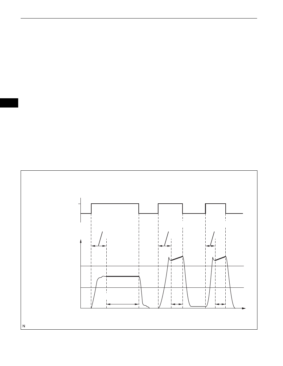
Sensor current detection monitor
A rich air-fuel mixture causes a low A/F sensor current, and a lean air-fuel mixture causes a high A/F
sensor current. Therefore, the sensor output becomes low during acceleration, and it becomes high
during deceleration with the throttle valve fully closed. The ECM monitors the A/F sensor current during
fuel-cut and detects any abnormal current values.
If the A/F sensor output is 3.6 mA or more for more than 3 seconds of cumulative time, the ECM interprets
this as a malfunction in the A/F sensor and sets DTC P2195 or P2197 (high-side stuck). If the A/F sensor
output is 1.4 mA or less for more than 3 seconds of cumulative time, the ECM sets DTC P2196 or P2198
(low-side stuck).
Air Fuel Ratio Sensor Current Monitor
Cumulative Time "t" = t1 + t2 =3 seconds or more
Fuel-Cut
ON
OFF
Delay (3 seconds)
Delay (3 seconds)
Delay (3 seconds)
3 seconds or more
Normal Sensor Output
Abnormal Sensor Output
Time
Sensor Current (mA)
High Side Threshold
Low Side Threshold
t1
t2
A107165E01
Нет комментариевНе стесняйтесь поделиться с нами вашим ценным мнением.
Текст