Toyota FJ Cruiser (GSJ 10, 15 series). Manual — part 308
LIGHTING – TURN SIGNAL FLASHER ASSEMBLY
LI–123
LI
TURN SIGNAL FLASHER
ASSEMBLY
ON-VEHICLE INSPECTION
1.
INSPECT TURN SIGNAL FLASHER CIRCUIT
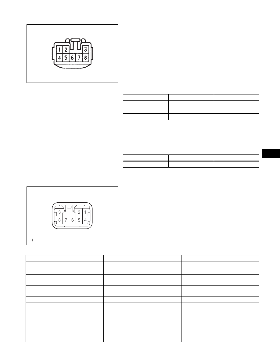
(a) Check the power source circuit and ground circuit.
(1) Disconnect the turn signal flasher connector.
(2) Measure the voltage and check the results in
accordance with the value(s) in the table below.
Standard Voltage
If the result is not as specified, there may be a
malfunction on the wire harness side.
(3) Measure the resistance and check the result in
accordance with the value(s) in the table below.
Standard Resistance
If the result is not as specified, there may be a
malfunction on the wire harness side.
(b) Check the output operation signal.
(1) Reconnect the turn signal flasher connector.
(2) Measure the voltage and check the results in
accordance with the value(s) in the table below.
Standard Voltage
Connector Front Side:
E068703E05
Tester Connection
Condition
Specified Condition
1 - Body ground
Ignition switch off
0 V
1 - Body ground
Ignition switch ON
11 to 14 V
4 - Body ground
Always
11 to 14 V
Tester Connection
Condition
Specified Condition
7 - Body ground
Always
Below 1
Ω
Connector Back Side:
E101506E01
Tester Connection
Condition
Specified Condition
2 - Body ground
Hazard warning switch OFF
Below 1 V
2 - Body ground
Hazard warning switch ON
11 to 14 V (60 to 120 times per minute)
2 - Body ground
Ignition switch ON and turn signal switch
(right turn) OFF
Below 1 V
2 - Body ground
Ignition switch ON and turn signal switch
(right turn) ON
11 to 14 V (60 to 120 times per minute)
3 - Body ground
Hazard warning switch OFF
Below 1 V
3 - Body ground
Hazard warning switch ON
11 to 14 V (60 to 120 times per minute)
3 - Body ground
Ignition switch ON and turn signal switch
(left turn) OFF
Below 1 V
3 - Body ground
Ignition switch ON and turn signal switch
(left turn) ON
11 to 14 V (60 to 120 times per minute)
5 - Body ground
Ignition switch ON and turn signal switch
(left turn) OFF
11 to 14 V

LI–124
LIGHTING – TURN SIGNAL FLASHER ASSEMBLY
LI
5 - Body ground
Ignition switch ON and turn signal switch
(left turn) ON
Below 1 V
6 - Body ground
Ignition switch ON and turn signal switch
(right turn) OFF
11 to 14 V
6 - Body ground
Ignition switch ON and turn signal switch
(right turn) ON
Below 1 V
8 - Body ground
Hazard warning switch OFF
11 to 14 V
8 - Body ground
Hazard warning switch ON
Below 1 V
Tester Connection
Condition
Specified Condition

LIGHTING – HEADLIGHT RELAY
LI–125
LI
HEADLIGHT RELAY
ON-VEHICLE INSPECTION
1.
INSPECT HEADLIGHT RELAY
(a) Check the resistance.
(b) Using an ohmmeter, measure the resistance
between the terminals.
Standard Resistance
If the result is not as specified, replace the headlight
relay.
Battery
Ohmmeter
E109076E01
Tester Connection
Specified Condition
3 - 5
10 k
Ω or higher
3 - 5
Below 1
Ω
(Battery voltage applied to terminals
1 and 2)
LI–126
LIGHTING – HEADLIGHT DIMMER RELAY
LI
HEADLIGHT DIMMER RELAY
ON-VEHICLE INSPECTION
1.
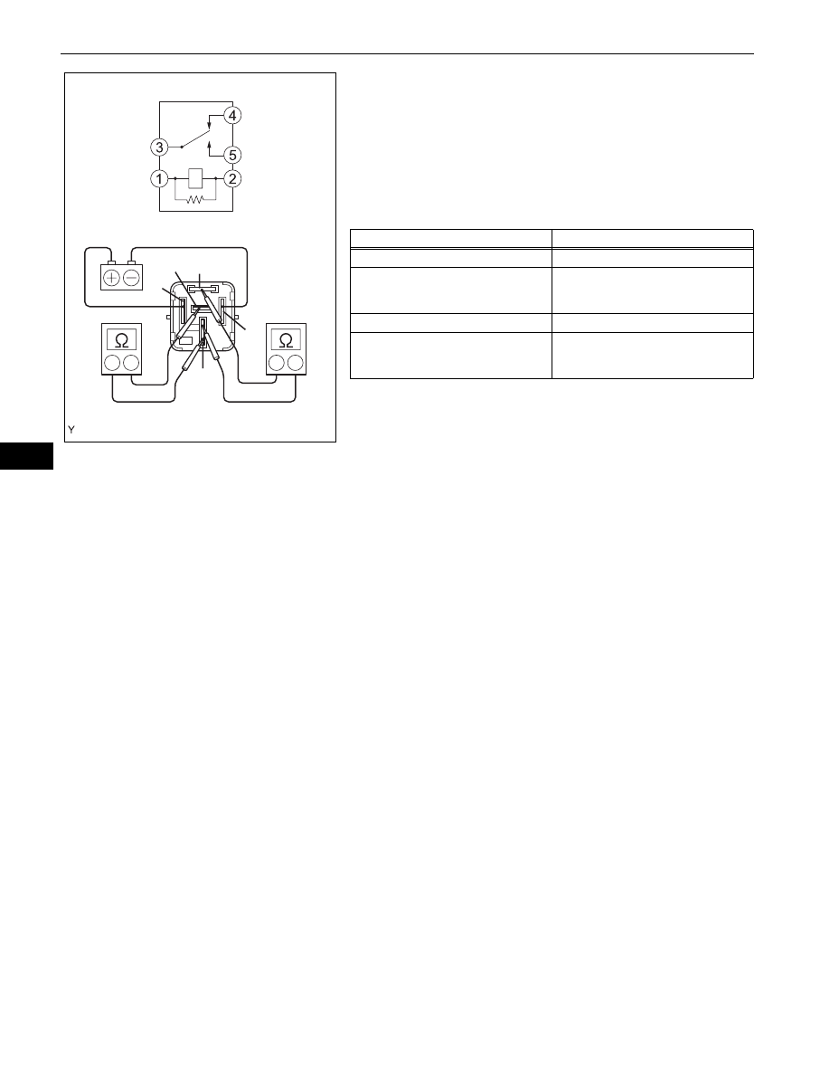
INSPECT HEADLIGHT DIMMER RELAY
(a) Check the resistance.
(1) Using an ohmmeter, measure the resistance
between the terminals.
Standard Resistance
If the result is not as specified, replace the
headlight dimmer relay.
Ohmmeter
Battery
Ohmmeter
1
2
3
4
5
E106620E01
Tester Connection
Specified Condition
3 - 4
Below 1
Ω
3 - 4
10 k
Ω or higher
(Battery voltage applied to terminals
1 and 2)
3 - 5
10 k
Ω or higher
3 - 5
Below 1
Ω
(Battery voltage applied to terminals
1 and 2)
Нет комментариевНе стесняйтесь поделиться с нами вашим ценным мнением.
Текст