Toyota FJ Cruiser (GSJ 10, 15 series). Manual — part 283

LIGHTING – LIGHTING SYSTEM
LI–29
LI
(a) Remove the HEAD relay from the engine room R/B No.
2.
(b) Disconnect the 1B main body ECU connector.
(c) Measure the resistance.
Standard resistance
(d) Reinstall the HEAD relay.
(e) Reconnect the main body ECU connector.
NG
OK
4
CHECK HARNESS AND CONNECTOR (HEADLIGHT RELAY - MAIN BODY ECU)
1
2
3
4
5
6
7
8
9 10 11 12 13
Engine Room R/B No. 2:
Wire Harness Side:
Front View
HRLY
1B
Main Body ECU Connector
B136079E01
Tester connection
Specified Condition
HEAD relay terminal 2 - 1B-8 (HRLY)
Below 1
Ω
HEAD relay terminal 2 or 1B-8 (HRLY)
- Body ground
10 k
Ω or higher
REPAIR OR REPLACE HARNESS OR
CONNECTOR
PROCEED TO NEXT CIRCUIT INSPECTION SHOWN IN PROBLEM SYMPTOMS TABLE

LI–30
LIGHTING – LIGHTING SYSTEM
LI
SYSTEM DESCRIPTION
The main body ECU controls the DRL relay.
WIRING DIAGRAM
INSPECTION PROCEDURE
(a) Connect the intelligent tester with CAN VIM to the DLC3.
(b) Turn the ignition switch ON.
(c) Turn the intelligent tester main switch on.
(d) Select the item below in the ACTIVE TEST and then
check the relay operation.
BODY
OK:
Headlight assembly (low) illuminates.
OK
NG
(a) Remove the DRL fuse from the engine room R/B No. 2.
DRL Relay Circuit
1
PERFORM ACTIVE TEST BY INTELLIGENT TESTER (DRL RLY)
HRLY
DRL
DRL
HEAD
To Headlight LH
To Headlight RH
To Battery
H-ON
Main Body ECU
B136081E01
Item
Test Details
Diagnostic Note
DRL RLY
DRL relay ON / OFF
-
PROCEED TO NEXT CIRCUIT INSPECTION
SHOWN IN PROBLEM SYMPTOMS TABLE
2
INSPECT FUSE (DRL FUSE)
LIGHTING – LIGHTING SYSTEM
LI–31
LI
(b) Measure the resistance.
Standard resistance:
Below 1
Ω
(c) Reinstall the DRL fuse.
NG
OK
(a) Remove the DRL relay from the engine room R/B No. 4.
(b) Measure the resistance.
Standard resistance
(c) Reinstall the DRL relay.
NG
OK
(a) Remove the DRL relay from the engine room R/B No. 4.
(b) Measure the voltage.
Standard voltage
(c) Reinstall the DRL relay.
NG
OK
REPLACE FUSE
3
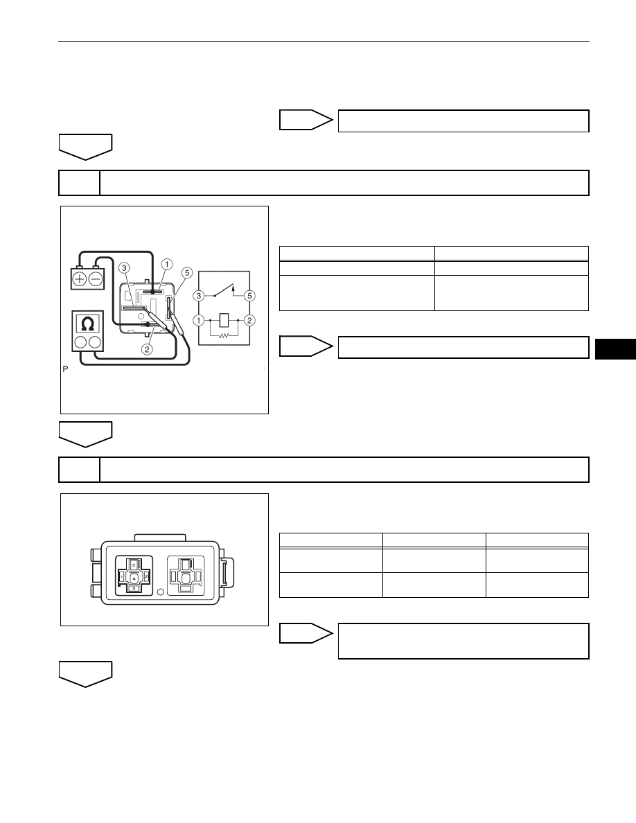
INSPECT DAYTIME RUNNING LIGHT RELAY
Battery
Ohmmeter
E109076E03
Tester Connection
Specified Condition
3 - 5
10 k
Ω or higher
3 - 5
Below 1
Ω
(When battery voltage is applied
between terminals 1 and 2)
REPLACE DAYTIME RUNNING LIGHT RELAY
4
CHECK HARNESS AND CONNECTOR (BATTERY - DAYTIME RUNNING LIGHT RELAY)
Engine Room R/B No. 4:
B136082E01
Tester connection
Condition
Specified Condition
DRL relay terminal 1 -
Body round
Light control switch is
in HEAD position
11 to 14 V
DRL relay terminal 1 -
Body round
Light control switch is
in OFF or TAIL position
Below 1 V
REPAIR OR REPLACE HARNESS OR
CONNECTOR

LI–32
LIGHTING – LIGHTING SYSTEM
LI
(a) Remove the DRL relay from the engine room R/B No. 4.
(b) Disconnect the 1B main body ECU connector.
(c) Measure the resistance.
Standard resistance
(d) Reinstall the DRL relay.
(e) Reconnect the main body ECU connector.
NG
OK
(a) Remove the DRL relay from the engine room R/B No. 4.
(b) Disconnect the A23 and A24 headlight connectors.
(c) Measure the resistance.
Standard resistance
(d) Reinstall the DRL relay.
(e) Reconnect the headlight connectors.
NG
5
CHECK HARNESS AND CONNECTOR (DAYTIME RUNNING LIGHT RELAY - MAIN BODY
ECU)
1
2
3
4
5
6
7
8
9 10 11 12 13
Front View
Wire Harness Side:
1B
Engine Room R/B No. 4:
Main Body ECU Connector
B136083E01
Tester Connection
Specified Condition
DRL relay terminal 2 - 1B-3 (H-ON)
Below 1
Ω
DRL relay terminal 2 or 1B-3 (H-ON) -
Body ground
10 k
Ω or higher
REPAIR OR REPLACE HARNESS OR
CONNECTOR
6
CHECK HARNESS AND CONNECTOR (DAYTIME RUNNING LIGHT RELAY - HEADLIGHT,
BODY GROUND)
Engine Room R/B No. 4:
Headlight Connector
Front View
*1: LH
*2: RH
Wire Harness Side:
A23
A24
*
1
*
2
B136084E01
Tester Connection
Specified Condition
DRL relay terminal 3 - A23-3
Below 1
Ω
DRL relay terminal 3 or A23-3 - Body
ground
10 k
Ω or higher
DRL relay terminal 3 - A24-3
Below 1
Ω
DRL relay terminal 3 or A24-3 - Body
ground
10 k
Ω or higher
DRL relay terminal 5 - Body ground
Below 1
Ω
REPAIR OR REPLACE HARNESS OR
CONNECTOR
Нет комментариевНе стесняйтесь поделиться с нами вашим ценным мнением.
Текст