Toyota FJ Cruiser (GSJ 10, 15 series). Manual — part 229

1GR-FE FUEL – FUEL PUMP
FU–31
FU
3.
REMOVE FUEL PUMP ASSEMBLY
(a) Disengage the clamp, then disconnect the
connector.
(b) Disengage the 5 claws and separate the fuel pump
from the fuel pump case.
(c) Disconnect the connector from the fuel pump.
4.
REMOVE FUEL PUMP FILTER
(a) Remove the fuel filter from the fuel pump.
5.
REMOVE FUEL PRESSURE REGULATOR
ASSEMBLY
(a) Remove the fuel pressure regulator and the 2 O-
rings.
A129894
A129897
A129898
Fuel
Pump
Fuel Filter
A129899E01
O-ring
A129900E02

FU–32
1GR-FE FUEL – FUEL PUMP
FU
INSPECTION
1.
INSPECT FUEL PUMP ASSEMBLY
(a) Check the resistance.
(1) Using an ohmmeter, measure the resistance
between the terminals.
Standard resistance:
0.2 to 3.0
Ω at 20°C (68°F)
If the result is not as specified, replace the fuel
pump.
REASSEMBLY
1.
INSTALL FUEL PRESSURE REGULATOR ASSEMBLY
(a) Install a new O-ring into the fuel pump case.
(b) Install a new O-ring onto the fuel pressure regulator.
(c) Install the pressure regulator.
2.
INSTALL FUEL PUMP FILTER ASSEMBLY
(a) Install the fuel filter onto the fuel pump.
3.
INSTALL FUEL PUMP ASSEMBLY
(a) Connect the fuel filter to the fuel pump.
(b) Engage the 5 claw fittings and install the fuel pump
onto the fuel pump case.
A129901
O-ring
A129900E02
Fuel
Pump
Fuel Filter
A129899E01
A129898
G036091

1GR-FE FUEL – FUEL PUMP
FU–33
FU
(c) Engage the clamp, then connect the connector.
4.
INSTALL NO. 1 FUEL SUB-TANK
(a) Install the connector and engage the clamp.
(b) Engage the 5 claws and install the fuel pump tank.
5.
INSTALL FUEL SENDER GAUGE ASSEMBLY
(a) Engage the claw and install the sender gauge by
sliding it in the direction as shown in the illustration.
(b) Connect the connector.
A129894
A129893
A129892
G036094
A129890
FU–34
1GR-FE FUEL – FUEL PUMP
FU
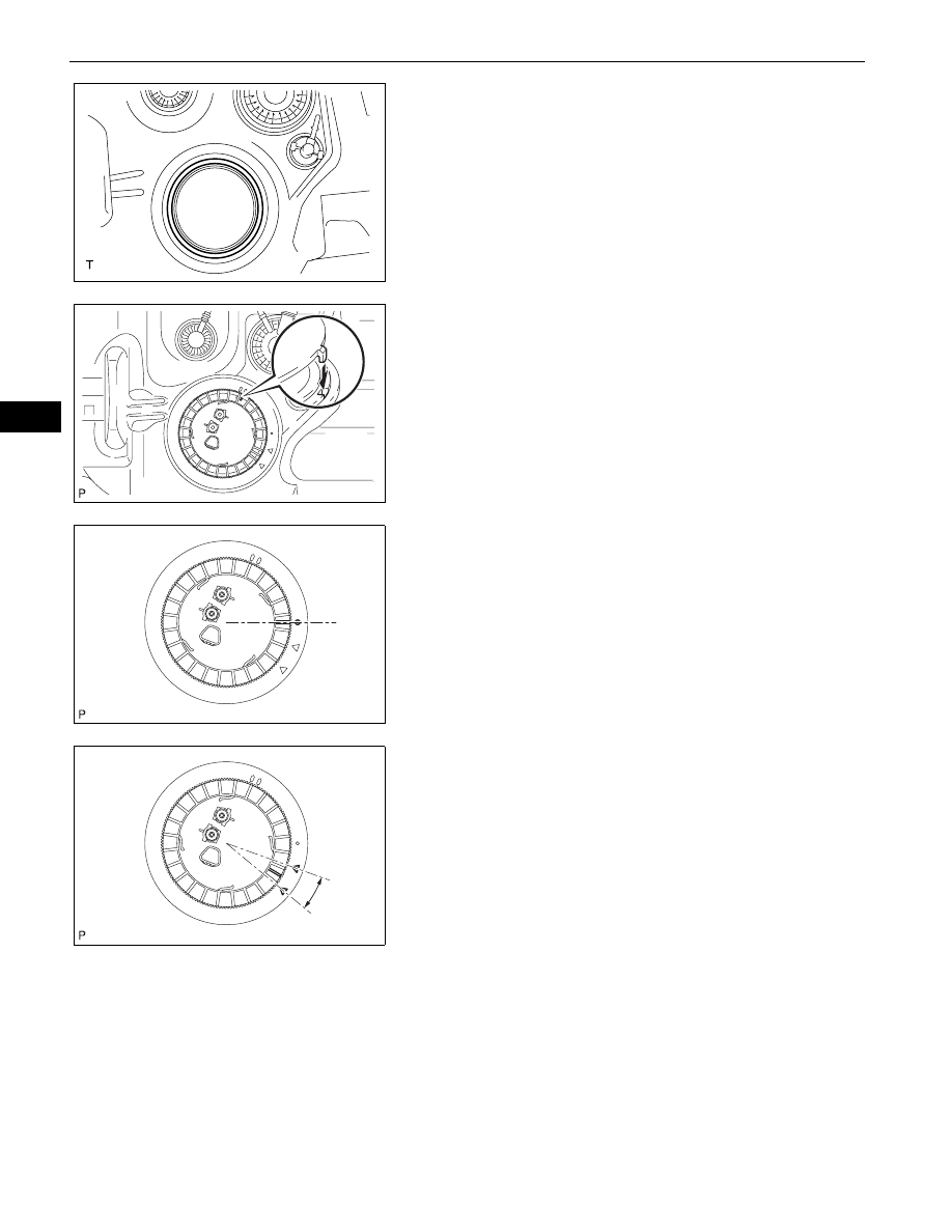
INSTALLATION
1.
INSTALL FUEL SUCTION WITH PUMP AND GAUGE
TUBE ASSEMBLY
(a) Install a new gasket onto the fuel tank.
(b) Set the fuel suction tube assembly to the fuel tank.
NOTICE:
Do not bend the arm of the fuel sender gauge.
(c) Fit the spline of the fuel suction tube assembly into
the keyway of the fuel tank.
(d) Install a new retainer.
(1) Align the mark on a new retainer with the rib on
the fuel tank as shown in the illustration.
(2) Using SST, turn the retainer 740
° to 760°
clockwise (more than 2 turns), and position the
mark on the retainer within range A to install it.
SST
09808-14020 (09808-01410, 09808-
01420, 09808-01430)
HINT:
Align the tips of the SST with the ribs on the
retainer.
2.
INSTALL FUEL TANK MAIN TUBE AND FUEL TANK
RETURN TUBE (See page
)
3.
INSTALL FUEL TANK ASSEMBLY (See page
4.
REMOVE FUEL TANK VENT HOSE (See page
)
5.
CONNECT FUEL TANK MAIN TUBE AND FUEL TANK
RETURN TUBE (See page
)
6.
CONNECT FUEL TANK BREATHER TUBE SUB-
ASSEMBLY (See page
)
7.
CONNECT FUEL TANK TO FILLER PIPE HOSE (See
page
)
A129944
A129920
A129921
A129930
Нет комментариевНе стесняйтесь поделиться с нами вашим ценным мнением.
Текст