Toyota FJ Cruiser (GSJ 10, 15 series). Manual — part 179

1GR-FE ENGINE MECHANICAL – ENGINE UNIT
EM–147
EM
(i)
Mark the front side of the each connecting cap bolt
with paint.
(j)
Retighten the cap bolts 90
° as shown in the
illustration.
NOTICE:
Do not turn the crankshaft.
(k) Remove the 2 bolts, connecting rod cap and lower
bearing.
(l)
Measure the plastigage at its widest point.
Standard oil clearance:
0.026 to 0.046 mm (0.0010 to 0.0018 in.)
Maximum oil clearance:
0.066 mm (0.0025 in.)
NOTICE:
Completely remove the plastigage.
(m) When replacing the bearing, replace it with one with
the same number as marked on the connecting rod.
There are 4 sizes of standard bearings, marked "1",
"2", "3" and "4".
HINT:
Standard bearing center wall thickness
(n) Remove the 2 connecting rod cap bolts.
90°
90°
Front
Painted Mark
A075151E03
A075152E02
Number Mark
A126508E01
Mark
mm (in.)
"1"
1.484 to 1.487 (0.0584 to 0.0585)
"2"
1.487 to 1.490 (0.0585 to 0.0587)
"3"
1.490 to 1.493 (0.0587 to 0.0588)
"4"
1.493 to 1.496 (0.0588 to 0.0589)
A075150E01

EM–148
1GR-FE ENGINE MECHANICAL – ENGINE UNIT
EM
52. REMOVE PISTON SUB-ASSEMBLY WITH
CONNECTING ROD
(a) Using a ridge reamer, remove all the carbon from
the top of the cylinder.
(b) Push in the piston, connecting rod assembly and
upper bearing through the top of the cylinder block.
HINT:
•
Keep the bearings, connecting rod and cap
together.
•
Arrange the piston and connecting rod in the
correct order.
53. REMOVE CONNECTING ROD BEARING
54. REMOVE PISTON RING SET
(a) Using a piston ring expander, remove the 2
compression rings.
(b) Remove the 2 side rails and oil ring by hand.
55. REMOVE HOLE SNAP RING
(a) Using a small screwdriver, pry out the 2 snap rings.
56. REMOVE WITH PISTON SUB-ASSEMBLY
(a) Gradually heat the piston to approximately 80
°C
(176
°F).
A076043E01
A076044E01
P012403E01
80°C (176°F)
A076045E07
1GR-FE ENGINE MECHANICAL – ENGINE UNIT
EM–149
EM
(b) Using a plastic-faced hammer and brass bar, lightly
tap out the piston pin and remove the connecting
rod.
HINT:
•
The piston and pin are a matched set.
•
Arrange the pistons, pins, rings, connecting rods
and bearings in the correct order.
57. INSPECT CRANKSHAFT THRUST CLEARANCE
(a) Using a dial indicator, measure the thrust clearance
while prying the crankshaft back and forth with a
screwdriver.
Standard thrust clearance:
0.04 to 0.24 mm (0.0016 to 0.0094 in.)
Maximum thrust clearance:
0.30 mm (0.0118 in.)
If the thrust clearance is greater than the maximum,
replace the pair of the thrust washers or crankshaft.
HINT:
Thrust washer thickness:
1.93 to 1.98 mm (0.0760 to 0.0780 in.)
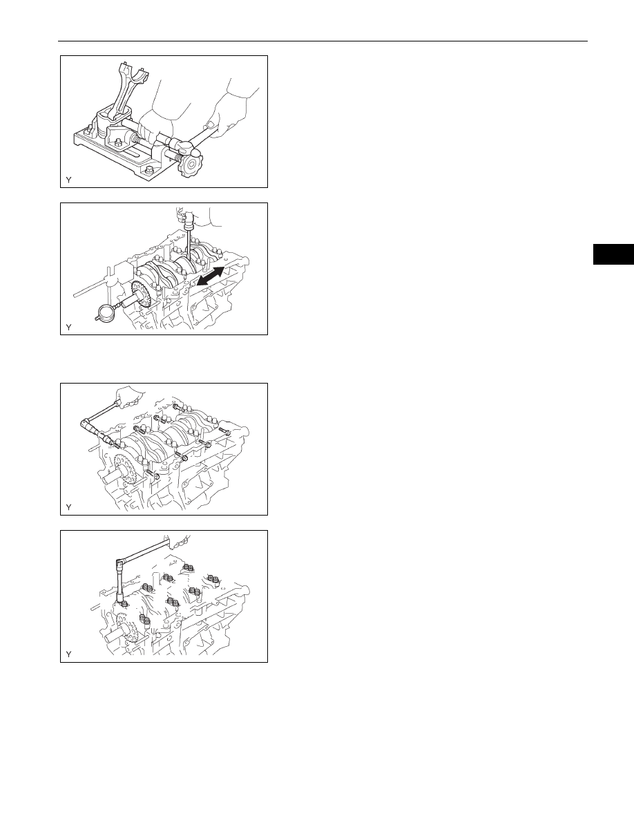
58. INSPECT CRANKSHAFT OIL CLEARANCE
(a) Using several steps, uniformly loosen and remove
the 8 main bearing cap bolts and seal washers in
the sequence shown in the illustration.
(b) Using several steps, uniformly loosen and remove
the 16 main bearing cap bolts in the sequence
shown in the illustration.
A076046E01
A076047E01
6
1
7
8
5
2
3
4
A076048E01
1
3
2
10
9
4
5
6
7
8
13
14
12
11
15
16
A076049E01

EM–150
1GR-FE ENGINE MECHANICAL – ENGINE UNIT
EM
(c) Using a screwdriver, pry out the main bearing caps.
Remove the 4 main bearing caps and lower
bearings.
NOTICE:
•
Pull up the main bearing cap by turning it to
the right and left little by little.
•
Be careful not to damage the joint surfaces of
the cylinder block and the main bearing cap.
(d) Lay a strip of plastigage across each journal.
(e) Examine the front marks and numbers, check the
sequence order is as shown and install the bearing
caps onto the cylinder block.
(f)
Apply a light coat of engine oil to the threads of
bearing cap bolts.
(g) Temporarily install the 8 main bearing cap bolts in
the inside positions.
(h) Install the main bearing caps. Tighten the 2 bolts for
each bearing cap until the clearance between the
bearing cap and the cylinder block is under 6 mm
(0.23 in.).
Joint Surface
A121032E01
Plastigage
A076066E02
A076067E01
Less than 6 mm
A076069E02
Нет комментариевНе стесняйтесь поделиться с нами вашим ценным мнением.
Текст