Toyota Corolla (2004+). Manual — part 92

14-157
ENGINE MECHANICAL
- CYLINDER BLOCK ASSY (April, 2003)
(b) Using a feeler gauge, measure the end gap.
Standard end gap:
0.25 to 0.35 mm (0.0098 to 0.0138 in.) for No. 1 ring
0.35 to 0.50 mm (0.0138 to 0.0197 in.) for No. 2 ring
0.15 to 0.40 mm (0.0059 to 0.0157 in.) for oil ring
Maximum end gap:
1.05 mm (0.0413 in.) for No. 1 ring
1.20 mm (0.0472 in.) for No. 2 ring
EM7639
F
If the end gap is greater than maximum, replace the
piston ring.
F
If the end gap is greater than maximum, even with
a new piston ring, replace the cylinder block.
20. INSPECT CONNECTING ROD SUB-ASSY
(a) Using a connecting rod aligner and feeler gauge, check
the connecting rod alignment.
(1)
Check for out-of-alignment.
Maximum out-of-alignment:
0.05 mm (0.0020 in.) per 100 mm (3.94 in.)
If out-of-alignment is greater than maximum, replace the con-
necting rod assembly.
A62804
(2)
Check for twist.
Maximum twist:
0.05mm (0.0020 in.) per 100 mm (3.94 in.)
If twist is greater than maximum, replace the connecting rod as-
sembly.
A62805
21. INSPECT CONNECTING ROD BOLT
(a) Using a vernier caliper, measure the tension portion diam-
eter of the bolts.
Standard diameter:
6.6 to 6.7 mm (0.260 to 0.264 in.)
Maximum diameter: 6.4 mm (0.252 in.)
If the diameter is less than maximum, replace the connecting
rod bolt.
A01470

14-158
ENGINE MECHANICAL
- CYLINDER BLOCK ASSY (April, 2003)
22. INSPECT CRANKSHAFT
(a) Using a dial indicator and V-blocks, measure the circle
runout, as shown in the illustration.
Maximum circle runout: 0.03 mm (0.0012 in.)
If the circle runout is greater than maximum, replace the crank-
shaft.
A64828
(b) Using a micrometer, measure the diameter of each main
journal at the points shown in the illustration.
Diameter: 47.988 to 48.000 mm (1.8893 to 1.8898 in.)
If the diameter is not as specified, check the crankshaft oil clear-
ance.
(c)
Check each main journal for taper and out-of-round as
shown.
Maximum taper and out-of-round:
ZF6927
0.02 mm (0.0008 in.)
If the taper and out-of-round is greater than maximum, replace
the crankshaft.
(d) Using a micrometer, measure the diameter of each crank
pin at the points shown in the illustration.
Diameter: 43.992 to 44.000 mm (1.7320 to 1.7323 in.)
If the diameter is not as specified, check the connecting rod oil
clearance.
(e) Check each crank pin for taper and out-of-round as
shown.
Maximum taper and out-of-round:
ZF6928
0.02 mm (0.0008 in.)
If the taper and out-of-round is greater than maximum, replace
the crankshaft.
23. INSPECT CRANKSHAFT BEARING CAP SET BOLT
(a) Using a vernier caliper, measure the tension portion diam-
eter of the bolts.
Standard diameter: 7.3 to 7.5 mm (0.287 to 0.295 in.)
Minimum diameter: 7.3 mm (0.287 in.)
If the diameter is greater than minimum, replace the crankshaft
bearing cap set bolt.
A01194

14-159
ENGINE MECHANICAL
- CYLINDER BLOCK ASSY (April, 2003)
24. INSPECT CRANKSHAFT OIL CLEARANCE
Plastigage
NOTICE:
Do not turn the crankshaft.
(a) Clean each main journal and bearing.
(b) Place the crankshaft on the cylinder block.
(c)
Lay a strip of the Plastigage across each journal.
A11780
(d) Using SST, tighten the bolts in several passes, in the se-
quence shown, by the specified torque.
SST
09011-38121
8
4
2
6
10
Torque: 44 N m (449 kgf cm, 33 ft lbf)
7
3
1
5
9
A64968
(e) Mark the front of the bearing cap bolts with paint.
(f)
Retighten the bearing cap bolts by 90_ as shown in the
Engine
90_
illustration.
Front
(g) Check that the painted mark is now at a 90_ angle to the
front.
Paint Mark
A65715
(h) Tighten the other 10 bolts for the bearing cap.
Torque: 19 N m (194 kgf cm, 14 ft lbf)
(i)
Remove the 10 bolts.
A64817
(j)
Uniformly loosen the 10 bearing cap bolts, in several
passes, in the sequence shown in the illustration.
SST
09011-38121
3
7
9
5
1
4
8
10
6
2
A64968

14-160
ENGINE MECHANICAL
- CYLINDER BLOCK ASSY (April, 2003)
(k)
Measure the Plastigage at its widest point.
Standard oil clearance:
0.015 to 0.032 mm (0.0006 to 0.0013 in.)
Minimum oil clearance: 0.05 mm (0.0020 in.)
NOTICE:
Completely remove the Plastigage.
F
If the oil clearance is greater than minimum, replace
the crankshaft bearing.
A11781
F
If necessary, replace the crankshaft.
HINT:
If replacing a bearing, select a new one having the same num-
Cylinder Block:
ber. If the number of the bearing cannot be determined, calcu-
No. 1
No. 2
No. 3
No. 4
No. 5
late the correct bearing number by adding together the num-
bers imprinted on the cylinder block and crankshaft, then select
a new bearing having the calculated number. There are 4 sizes
of standard bearings, marked ”1”, ”2”, ”3” and ”4” accordingly.
Cylinder block (A)
+
0 to 2
3 to 5
6 to 8
9 to 11
Crankshaft (B)
Use bearing
”1”
”2”
”3”
”4”
EXAMPLE:
Cylinder block ”3” (A) + Crankshaft ”4” (B) = Total number 7 (Use
Crankshaft:
bearing ”3”)
No. 1
No. 2
Item
Mark
mm (in.)
No. 3
”0”
52.000 to 52.002 (2.0472 to 2.0473)
No. 4
No. 5
”1”
52.003 to 52.004 (2.0474 to 2.0474)
”2”
52.005 to 52.006 (2.0474 to 2.0475)
Cylinder block journal bore
”3”
52.007 to 52.009 (2.0475 to 2.0476)
diameter (A)
”4”
52.010 to 52.011 (2.0476 to 2.0477)
”5”
52.012 to 52.013 (2.0477 to 2.0478)
”6”
52.014 to 52.015 (2.0478 to 2.0478)
”0”
47.999 to 48.000 (1.8897 to 1.8898)
”1”
47.997 to 47.998 (1.8896 to 1.8897)
Crankshaft journal diameter
”2”
47.995 to 47.996 (1.8896 to 1.8896)
(B)
”3”
47.993 to 47.994 (1.8895 to 1.8895)
Bearing:
”4”
47.991 to 47.992 (1.8894 to 1.8894)
”5”
47.988 to 47.990 (1.8893 to 1.8894)
”1”
1.994 to 1.997 (0.0785 to 0.0786)
Standard bearing center wall
”2”
1.998 to 2.000 (0.0787 to 0.0787)
Mark
thickness
”3”
2.001 to 2.003 (0.0788 to 0.0789)
”4”
2.004 to 2.006 (0.0789 to 0.0790)
A64971

14-161
ENGINE MECHANICAL
- CYLINDER BLOCK ASSY (April, 2003)
25. INSTALL STRAIGHT PIN
(a) Using a plastic hammer, install the 9 straight pins to the
cylinder block.
Standard protrusion:
5 mm (0.197 in.) for straight pin A
7.5 mm (0.295 in.) for straight pin B
12 mm (0.472 in.) for straight pin C
8 mm (0.315 in.) for straight pin D
Front Side:
Lower Side:
Rear Side:
A
C
B
Bearing Cap Exhaust Side:
10
D
10
6
8
5
7.5
12
8
(0.197)
(0.295)
(0.472)
(0.315)
22
14
15
15
A
B
C
D
(mm (in.))
A64972

14-162
ENGINE MECHANICAL
- CYLINDER BLOCK ASSY (April, 2003)
26. INSTALL RING PIN
(a) Using a plastic hammer, install the 5 ring pins to the cylin-
der block.
Standard protrusion:
6 mm (0.236 in.) for ring pin A
7 mm (0.276 in.) for rIng pin B
10 mm (0.394 in.) for ring pin C
Front Side:
Upper Side:
B
A
B
Bearing Cap Front Side:
9
13
14
10
7
15
6
12
12
(0.394)
(0.236)
(0.276)
C
A
B
C
(mm (in.))
A64973

14-163
ENGINE MECHANICAL
- CYLINDER BLOCK ASSY (April, 2003)
27. INSTALL STUD BOLT
(a) Using torx socket wrench E5 and E7, install the 9 stud bolt
to the cylinder block.
Torque:
5.0 Nm (51 kgf cm, 44 in. lbf) for stud bolt A, C, D and
E
11 Nm (112 kgf cm, 8 ft lbf) for stud bolt B
Intake Side:
Upper Side:
B
A
Bearing Cap Lower Side:
D
C
E
D
15
15
52.5
14
38.5
12
31.5
8.5
27.5
10
22.5
12
9
8
9
A
B
C
D
E
(mm)
A64974
28. INSTALL W/PIN PISTON SUB-ASSY
(a) Using a small screwdriver, install a new snap ring at one
end of the piston pin hole.
HINT:
End Gap
Be sure that end the gap of the snap ring is aligned with the pin
hole cutout portion of the piston.
Pin Hole
Cutout Portion
End Gap
A64975

14-164
ENGINE MECHANICAL
- CYLINDER BLOCK ASSY (April, 2003)
(b) Heat the piston to 80 to 90_C (176 to 194_F).
A01187
(c)
Align the front marks on the piston with connecting rod,
then push in the piston with your thumb.
Front
Mark
A64976
(d) Using a small screwdriver, install a new snap ring at one
end of the piston pin hole.
HINT:
Be sure that the end gap of the snap ring is aligned with the pin
End Gap
hole cutout portion of the piston.
Pin Hole
Cutout Portion
End Gap
A64975
29. INSTALL PISTON RING SET
Cord Mark
HINT:
In case of reusing the piston rings, install them to the matched
pistons with the surfaces facing correctly.
(a) Install the oil ring expander and 2 side rails by hand.
(b) Using a piston ring expander, install the 2 compression
rings with the code mark facing upward.
Piston Ring
Code mark (No. 2 only): 2R
Expander
A62811
14-165
ENGINE MECHANICAL
- CYLINDER BLOCK ASSY (April, 2003)
(c)
Position the piston rings so that the ring ends are as
shown.
Upper Side Rail
Compression No. 2
Front
Mark
Compression No. 1
Lower Side Rail
and Expander
A64977
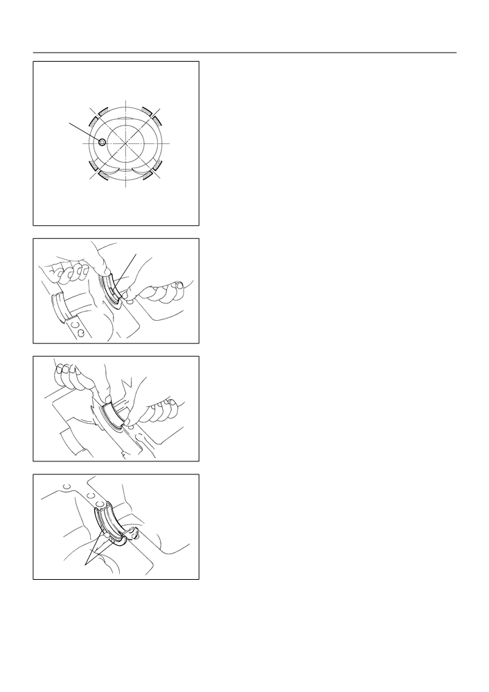
30. INSTALL CRANKSHAFT BEARING
Oil Groove
(a) Install the upper bearing with the oil groove on the cylin-
der block.
NOTICE:
Do not apply engine oil to the bearing and its contact sur-
face.
A01190
(b) Install the lower bearing on the bearing cap.
NOTICE:
Do not apply engine oil to the bearing and its contact sur-
face.
A01189
31. INSTALL CRANKSHAFT THRUST WASHER UPPER
(a) Install the 2 thrust washers under the No. 3 journal posi-
tion of the cylinder block with the oil grooves facing out-
ward.
Oil Groove
A01191

14-166
ENGINE MECHANICAL
- CYLINDER BLOCK ASSY (April, 2003)
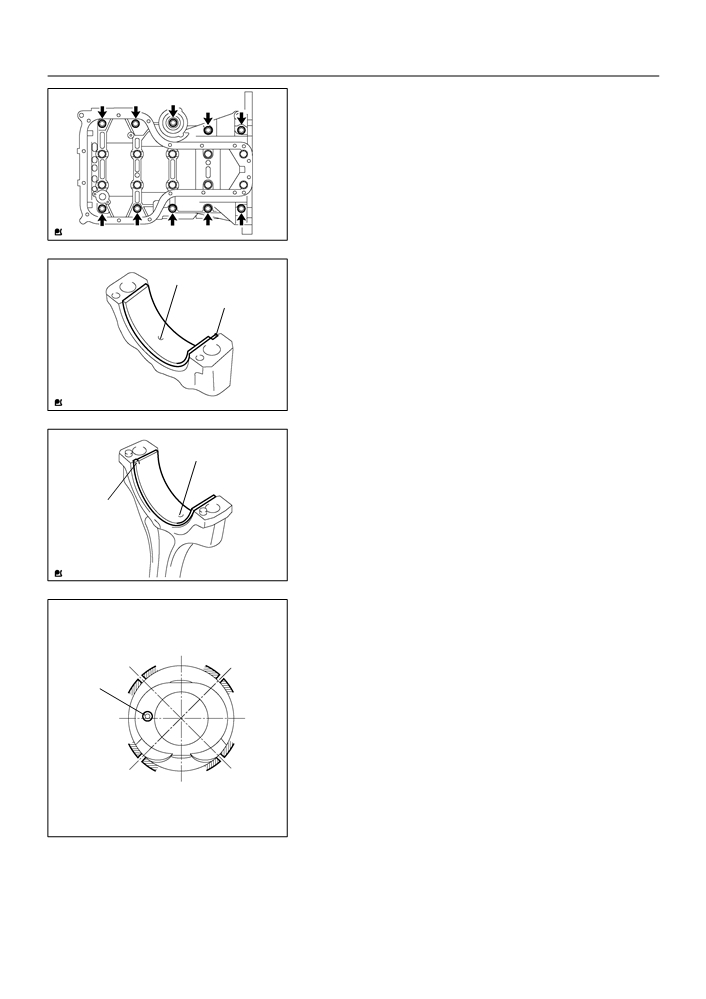
32. INSTALL CRANKSHAFT
(a) Apply engine oil to the upper bearing, then install the
crankshaft on the cylinder block.
(b) Apply a light coat of engine oil on the bolt threads, bolt
seats, and bearings of the bearing cap.
(c)
Install the crankshaft to the cylinder block.
A64820
(d) Apply the seal packing in the shape of the bead (Diameter
Seal Packing
2.5 to 3.5 mm (0.098 to 0.138 in.) consequently as shown
in the illustration.
Seal packing: Part No. 08826-00080 or equivalent
NOTICE:
F
Remove any oil from the contact surface.
F
Install the bearing cap sub-assembly within 3 min-
utes after applying the seal packing.
F
Do not put into engine oil within 2 hours of installa-
tion.
A01038
(e) Using SST, tighten the bolts in several passes, in the se-
quence shown, by the specified torque.
SST
09011-38121
8
4
2
6
10
Torque: 44 N m (449 kgf cm, 33 ft lbf)
7
3
1
5
9
A64968
(f)
Mark the front of the bearing cap bolts with paint.
(g) Retighten the bearing cap bolts by 90_ as shown in the
Engine
90_
illustration.
Front
(h) Check that the painted mark is now at a 90_ angle to the
front.
Paint Mark
A65715
14-167
ENGINE MECHANICAL
- CYLINDER BLOCK ASSY (April, 2003)
(i)
Tighten the other 10 bolts for the bearing cap.
Torque: 19 N m (194 kgf cm, 14 ft lbf)
A64817
33. INSTALL CONNECTING ROD BEARING
Oil Groove
(a) Align the connecting rod bearing claw with the oil groove
of the connecting rod cap.
Claw
(b) Install the connecting rod bearing in the connecting rod
cap.
NOTICE:
Do not apply engine oil to the bearing and its contact sur-
face.
A64978
(c)
Align the connecting rod bearing claw with the oil groove
of the connecting rod.
Oil Groove
(d) Install the connecting rod bearing in the connecting rod.
NOTICE:
Do not apply engine oil to the bearing and its contact sur-
Claw
face.
A64979
34. INSTALL CONNECTING ROD SUB-ASSY
(a) Position the piston rings so that the ring ends are as
Upper Side Rail
Compression No. 2
shown.
(b) Apply engine oil to the cylinder walls, pistons, and sur-
faces of the connecting rod bearings.
Front
Mark
(c)
Check the position of the piston ring ends.
Compression No. 1
Lower Side Rail
and Expander
A64977
14-168
ENGINE MECHANICAL
- CYLINDER BLOCK ASSY (April, 2003)
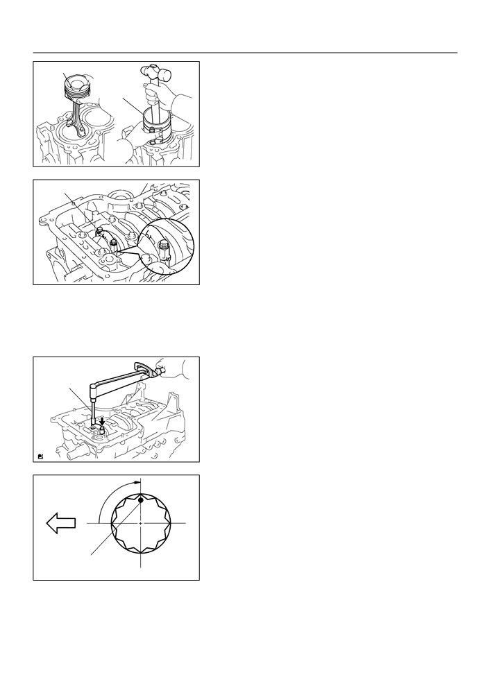
(d) Using a piston ring compressor, push the correctly num-
Front Mark
bered piston and connecting rod assemblies into each
Piston Ring
cylinder with the front mark of the piston facing forward.
Compressor
A62813
(e) Align the pin dowels of the connecting rod cap with the
Front Mark
pins of the connecting rod, then install the connecting rod.
NOTICE:
F
Clean the backside and surface of the connecting rod
cap bearing and let not stick the oils and fats.
F
Match the numbered connecting rod cap with the
same numbered connecting rod.
(f)
Check that the protrusion of the connecting rod cap is fac-
A65713
ing the correct direction.
(g) Apply a light coat of engine oil on the threads and under
the heads of the connecting rod cap bolts.
(h) Using SST, tighten the bolts in several passes by the spe-
cified torque.
SST
SST
09205-16010
Torque: 20 N m (204 kgf cm, 15 ft lbf)
A65714
(i)
Mark the front of the connecting cap bolts with paint.
(j)
Retighten the cap bolts by 90_ as shown in the illustration.
Engine
90_
(k)
Check that the crankshaft turns smoothly.
Front
Paint Mark
A65715
14-169
ENGINE MECHANICAL
- CYLINDER BLOCK ASSY (April, 2003)
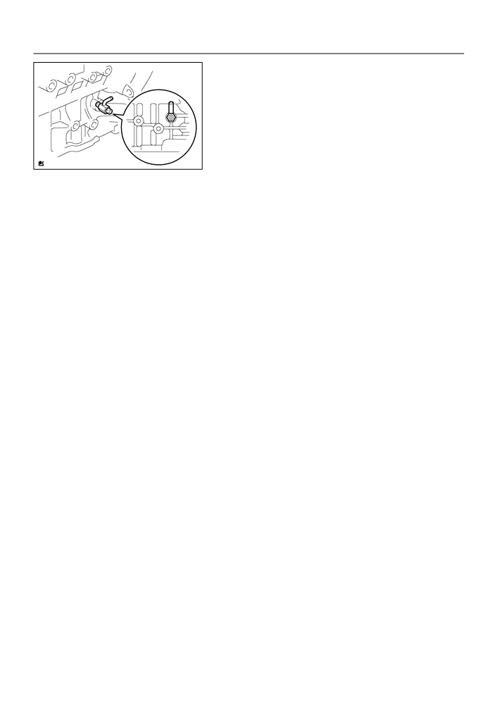
35. INSTALL CYLINDER BLOCK WATER DRAIN COCK
SUB-ASSY
(a) Apply 2 or 3 threads of adhesive to the cylinder block wa-
ter drain cock, then install it within 3 minutes.
Torque: 25 N m (255 kgf cm, 18 ft lbf)
Adhesive:
Part No. 08833-00080, THREE BOND 1344, LOCTITE
242 or equivalent
A64845
(b) After applying the specified torque, rotate the cylinder
block water drain cock clockwise until its drain port faces
downward.
NOTICE:
F
Do not put into coolant in an hour of installation.
F
Do not rotate the drain union more than 360
_ in (b),
and never loosen it after setting the union correctly.

14-108
ENGINE MECHANICAL
- CYLINDER HEAD GASKET
CYLINDER HEAD GASKET
140OK-05
COMPONENTS
Fan and Generator V Belt
54 (551, 40)
25 (255, 18)
37 (377, 27)
Vane Pump Assy
Terminal Cap
No. 1
Generator Assy
9.8 (100, 7)
7.0 (71, 62 in. lbf)
Clip
Cylinder Head Cover No. 2
52 (530, 38)
EFI Fuel Pipe Clamp
Engine Mounting Insulator RH
Fuel Tube Sub-assy
52 (530, 38)
Air Cleaner Hose No. 1
Water By-pass Hose No. 2
Heater Inlet Water Hose
Radiator Hose Inlet
Engine Under Cover RH
Clip
Union to Connector
Accelerator Control
Tube Hose
Cable Assy
Water By-pass Hose
Exhaust pipe Assy Front
_ Gasket
N·m (kgf·cm, ft·lbf)
: Specified torque
Compression Spring
43 (440, 32)
_ Non-reusable part
A64045
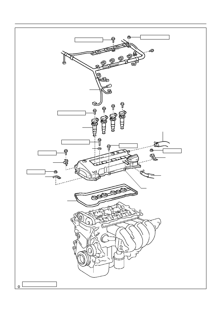
14-109
ENGINE MECHANICAL
- CYLINDER HEAD GASKET
9.0 (92, 80 in. lbf)
9.0 (92, 80 in. lbf)
Engine Wire
9.0 (92, 80 in. lbf)
Ignition Coil Assy
Ventilation Hose No. 2
9.0 (92, 80 in. lbf)
11 (112, 8)
Seal Washer
11 (112, 8)
11 (112, 8)
Clamp Bracket
Clamp Bracket
11 (112, 8)
Ventilation Hose
Clamp Bracket
Cylinder Head Cover
Sub-assy
Gasket
N·m (kgf·cm, ft·lbf)
: Specified torque
A64043
Большое спасибо!
Ваше мнение очень важно для нас.
Нет комментариевНе стесняйтесь поделиться с нами вашим ценным мнением.
Текст