Toyota Corolla (2004+). Manual — part 71

05-43
DIAGNOSTICS
-
SFI SYSTEM (April, 2003)
1. Fuel pump control circuit
05-278
Surging (Poor drivability)
2. Spark plug
18-2
3. Injector
05-149
1. Fuel pump control circuit
05-278
Engine stall (Soon after starting)
2. ISC valve circuit
05-251
1. Injector
05-149
Engine stall (After accelerator pedal released)
2. ISC valve circuit
05-251
3. ECM
01-30
1. Neutral start switch circuit*
40-6
Engine stall (When shifting N to D)
2. ISC valve circuit
05-251
*: A/T only
05-15
DIAGNOSTICS
- SFI SYSTEM (April, 2003)
05286-12
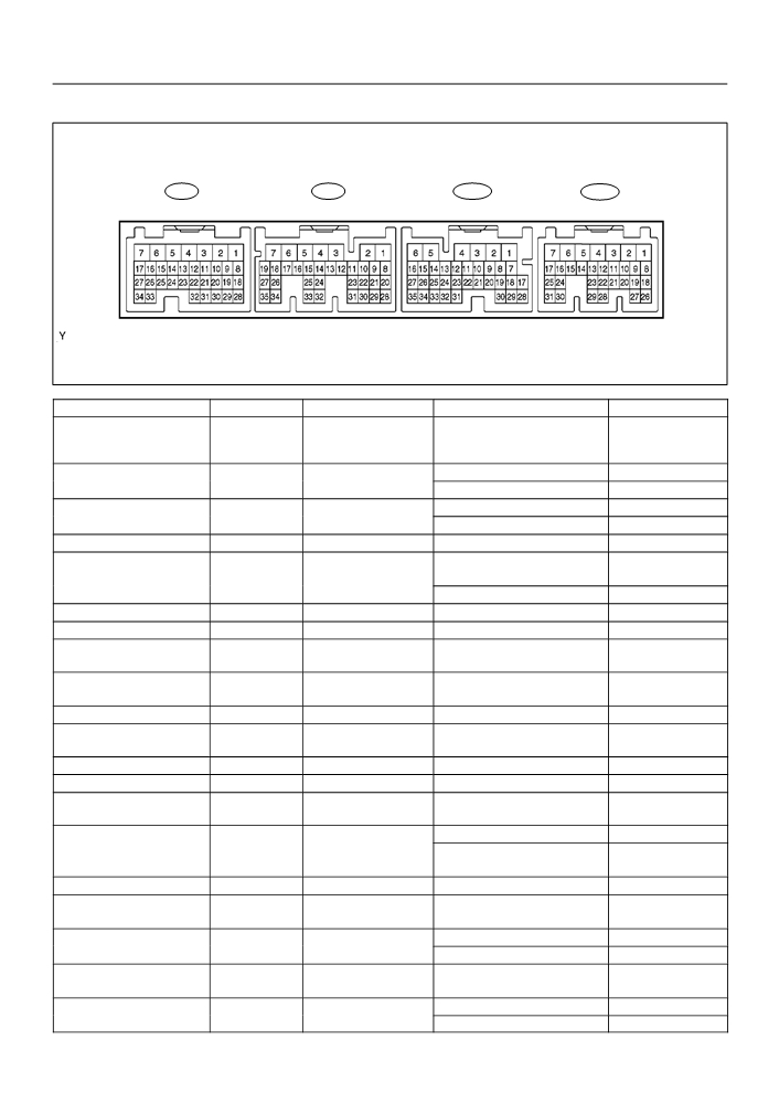
TERMINALS OF ECM
E3
E4
E5
E6
A66714
Symbols (Terminals No.)
Wiring Color
Terminal Description
Condition
STD Voltage (V)
Battery (for measuring the
BATT (E6 - 3) - E1 (E4 - 7)
R-W - BR
battery voltage and for the
Always
8 to 14
ECM memory)
IG switch ON
8 to 14
FC (E6
- 10) - E1 (E4
- 7)
G-R - BR
Fuel pump control
Idling
Below 1.5
Idling
8 to 14
W (E6
- 11) - E1 (E4
- 7)
R-Y - BR
MIL
IG switch ON
Below 3.5
+B (E6 - 1) - E1 (E4 - 7)
B - BR
Power source of ECM
IG switch ON
8 to 14
IG switch ON, Brake pedal de-
8 to 14
STP (E5 - 19) *1 - E1 (E4 - 7)
G-W - BR
Stop light switch
pressed
IG switch ON, Brake pedal released
Below 1.5
F/PS (E6 - 14) - E1 (E4 - 7)
Y - BR
Airbag sensor
IG switch ON
Pulse generation
STA (E4 - 9) - E1 (E4 - 7)
B - BR
Starter signal
Cranking
5.5 or more
Power steering oil pres-
PSW (E4 - 29) - E1 (E4 - 7)
L-R - BR
IG switch ON
8 to 14
sure sensor
Speed signal from com-
IG switch ON, rotate driving wheel
SPD (E5 - 17) - E1 (E4 - 7)
V-W - BR
Pulse generation
bination meter
slowly
TACH (E6 - 5) - E1 (E4 - 7)
B - BR
Engine speed
Idling
Pulse generation
Power source of sensor
VC (E3 - 18) - E2 (E3 - 28)
Y - BR
IG switch ON
4.5 to 5.5
(a specific voltage)
EVP (E3 - 12) - E01 (E3 - 7)
L-B - W-B
VSV for EVAP
IG switch ON
8 to 14
CCV (E5 - 1) - E01 (E3 - 7)
L - W-B
VSV for CCV
IG switch ON
9 to 14
VSV for Vapor pressure
TBP (E6 - 4) - E01 (E3 - 7)
R - W-B
IG switch ON
9 to 14
sensor
Ignition switch ON
2.9 to 3.7
PTNK (E6 - 21) - E2 (E3 - 28)
L - BR
Vapor pressure sensor
Apply vacuum 4.0 kPa (30 mmHG,
Below 0.5
1.18 in.Hg)
VG (E4 - 24) - EVG (E4 - 32)
G - L-W
Mass air flow sensor
Idling, A/C switch OFF
1.1 to 1.5
Heated oxygen sensor
Maintain engine speed at 2,500 rpm
Pulse generation
OX1A (E4 - 23) - E1 (E4 - 7)
B - BR
(Sensor 1)
for 2 min. after warning up
(See Page 05-96)
Heated oxygen sensor
Idling
Below 3.0
HT1A (E4
- 4) - E03 (E4
- 5)
P - W-B
heater (Sensor 1)
IG switch ON
9 to 14
Heated oxygen sensor
Maintain engine speed at 2,500 rpm
Pulse generation
OX1B (E4 - 21) - E1 (E4 - 7)
W - BR
(Sensor 2)
for 2 min. after warning up
(See Page 05-96)
Heated oxygen sensor
Idling
Below 3.0
HT1B (E5
- 4) - E03 (E4
- 5)
P-B - W-B
heater (Sensor 2)
IG switch ON
9 to 14

05-16
DIAGNOSTICS
- SFI SYSTEM (April, 2003)
Symbols (Terminals No.)
Wiring Color
Terminal Description
Condition
STD Voltage (V)
Engine coolant tempera-
Idling, Engine coolant temp. at 80°C
THW (E3 - 19) - E2 (E3 - 28)
W - BR
0.2 to 1.0
ture sensor
(176°F)
G22+ (E3 - 26)
Pulse generation
B - W
Camshaft position sensor
Idling
- NE- (E3 - 34)
(See Page 05-168)
Crankshaft position sen-
Pulse generation
NE+ (E3 - 27) - NE- (E3 - 34)
B - W
Idling
sor
See Page 05-168)
Intake air temperature
Idling, intake air temp. at 20°C
THA (E3 - 20) - E2 (E3 - 28)
Y-B - BR
0.5 to 3.4
sensor
(68°F)
IG switch ON, throttle valve fully
0.3 to 1.0
closed
VTA (E3
- 21) - E2 (E3
- 28)
LG - BR
Throttle position sensor
IG switch ON, throttle valve fully
3.2 to 4.9
open
#10 (E3 - 1) - E01 (E3 - 7)
Y - W-B
#20 (E3 - 2) - E01 (E3 - 7)
B - W-B
Injector
IG switch ON
8 to 14
#30 (E3 - 3) - E01 (E3 - 7)
W - W-B
#40 (E3 - 4) - E01 (E3 - 7)
L - W-B
IGT1 (E3 - 8) - E1 (E4 - 7)
R-L - BR
IGT2 (E3 - 9) - E1 (E4 - 7)
Y-G - BR
Ignition coil and igniter
Pulse generation
Idling
IGT3 (E3 - 10) - E1 (E4 - 7)
GR - BR
(ignition signal)
(See Page 05-177)
IGT4 (E3 - 11) - E1 (E4 - 7)
W - BR
IG switch ON
4.5 to 5.5
Ignition coil and igniter
IGF (E3 - 23) - E1 (E4 - 7)
L-Y - BR
(ignition confirmation sig-
Pulse generation
Idling
nal)
(See Page 05-177)
RSO (E3 - 5) - E01 (E3 - 7)
B-L - W-B
Idle air control valve
IG switch ON
9 to 14
OCV+ (E3 - 15)
Camshaft timing oil con-
Pulse generation
Y - B-Y
IG switch ON
- OCV- (E3 - 14)
trol valve
(See Page 05-44)
Pulse generation
KNK1 (E4 - 1) - EKNK (E4 - 2)
B - W
Knock sensor
Idling
(See Page 05-163)
TC (E6 - 20) - E1 (E4 - 7)
P-B - BR
Terminal TC of DLC 3
IG switch ON
9 to 14
SIL (E6 - 18) - E1 (E4 - 7)
L-R - BR
Terminal SIL of DLC3
Connect hand-held tester to DLC3
Pulse generation
*1: A/T only
05-520
DIAGNOSTICS
- SUPPLEMENTAL RESTRAINT SYSTEM (April, 2003)
05261-09
DTC
B1100/31
AIRBAG SENSOR ASSY MALFUNCTION
CIRCUIT DESCRIPTION
The airbag sensor assy center consists of a airbag sensor assy center, safing sensor, drive circuit, diagnosis
circuit and ignition control, etc.
It receives signals from the airbag sensor, judges whether or not the SRS must be activated, and detects
diagnosis system malfunction.
DTC B1100/31 is recorded when occurrence of a malfunction in the airbag sensor assy center is detected.
DTC No.
DTC Detecting Condition
Trouble Area
B1100/31
F Airbag sensor assy center malfunction
F Airbag sensor assy center
INSPECTION PROCEDURE
HINT:
When a malfunction code other than code B1100/31 is displayed at the same time, first repair the malfunction
indicated by the malfunction code other than code B1100/31.
INSPECTION PROCEDURE
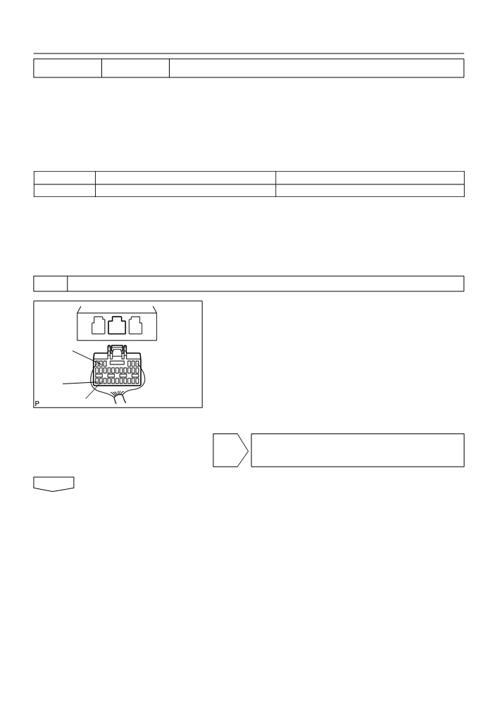
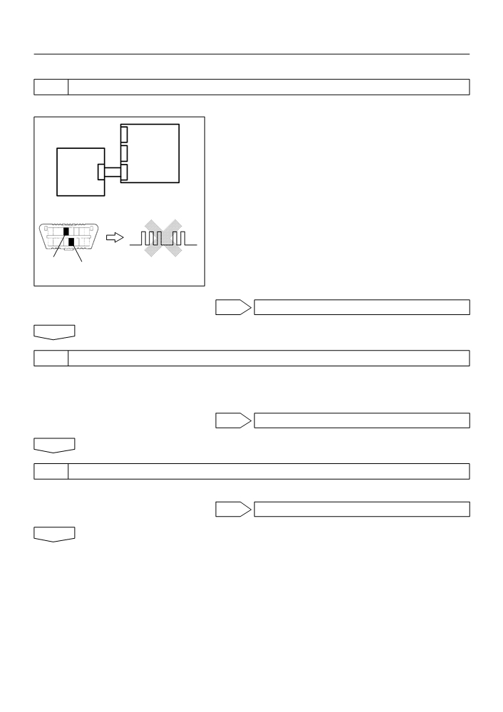
1
CHECK VOLTAGE AT IG2 OF AIRBAG SENSOR ASSY CENTER
(a) Disconnect the negative (-) terminal cable from the bat-
tery, and wait at least for 90 seconds.
(b) Disconnect the connector of the airbag sensor assy cen-
ter.
IG2
(c)
Connect the negative (-) terminal cable to the battery,
and wait at least for 2 seconds.
(d) Turn the ignition switch to ON.
E2
(e) Measure the voltage between E1 (E2) and IG2 of the air-
E1
bag sensor assy center connector.
H40065
OK:
Voltage: 10 - 14 V
NG CHECK CHECK THAT AN ABNORMALITY
OCCURS ON THE BATTERY AND CHARGING
SYSTEM
OK
05-521
DIAGNOSTICS
- SUPPLEMENTAL RESTRAINT SYSTEM (April, 2003)
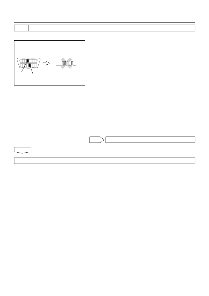
2
CHECK AIR BAG SENSOR ASSY CENTER
SST
09843-18040
(a) Turn the ignition switch to LOCK.
(b) Disconnect the negative (-) terminal cable from the bat-
tery, and wait at least for 90 seconds.
DLC3
DTC B1100/31
(c)
Connect the connectors of all the SRS components.
(d) Connect the negative (-) terminal cable to the battery,
and wait at least for 2 seconds.
(e) Turn the ignition switch to ON, and wait at least for 20 se-
CG Tc
conds.
H10600
H41086
(f)
Clear the DTC stored in memory (See page 05-424).
(g) Turn the ignition switch to LOCK, and wait at least for 20
seconds.
(h) Turn the ignition switch to ON, and wait at least for 20 se-
conds.
(i)
Check the DTC (See page 05-424).
OK:
DTC B1100/31 is not output.
HINT:
Codes other than code B1100/31 may be output at this time, but
they are not relevant to this check.
NG REPLACE AIR BAG SENSOR ASSY CENTER
OK
USE SIMULATION METHOD TO CHECK
05-522
DIAGNOSTICS
- SUPPLEMENTAL RESTRAINT SYSTEM (April, 2003)
055Z3-05
DTC
B1135/24
HARF CONNECTION IN AIRBAG SENSOR
ASSY CONNECTOR
CIRCUIT DESCRIPTION
The airbag sensor assy center detects partial connection of connector.
DTC B1135/24 is recorded when the airbag sensor assy center detects an open in the electrical connection
check mechanism of the airbag sensor connector or in the airbag sensor circuit.
DTC No.
DTC Detecting Condition
Trouble Area
F Malfunction of electrical connection check mechanism of
F Electrical connection check mechanism
B1135/24
airbag sensor assy center connector
F Airbag sensor assy center
F Airbag sensor assy center malfunction
INSPECTION PROCEDURE
1
CHECK AIRBAG SENSOR ASSY CENTER CONNECTOR
(a) Disconnect negative (-) terminal cable from the battery, and wait at least for 90 seconds.
(b) Check the connection of the airbag sensor assy center connectors.
NG CONNECT CONNECTORS
OK
2
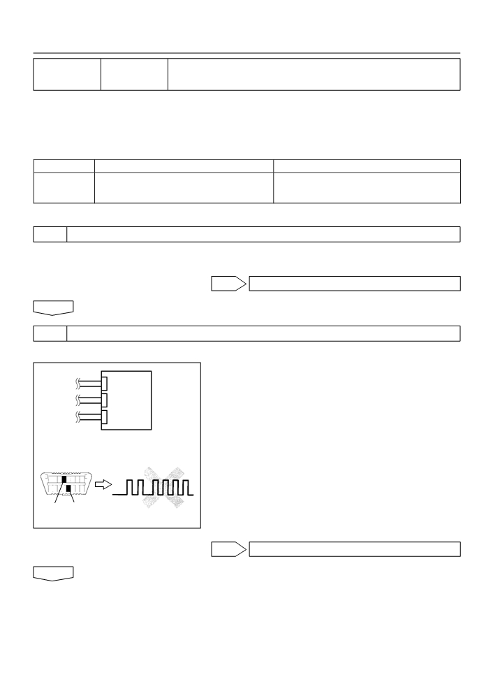
CHECK AIR BAG SENSOR ASSY CENTER
SST
09843-18040
(a) Connect the negative (-) terminal cable to the battery,
and wait at least for 2 seconds.
Airbag
(b) Turn the ignition switch to ON, and wait at least for 20 se-
Sensor
conds.
Assy
(c)
Clear the DTC stored in memory (See page 05-424).
Center
(d) Turn the ignition switch to LOCK, and wait at least for 20
seconds.
(e) Turn the ignition switch to ON, and wait at least for 20 se-
DTC B1135/24
DLC3
conds.
(f)
Check the DTC (See page 05-424).
OK:
DTC B1135/24 is not output.
CG Tc
HINT:
H40997
Codes other than code B1135/24 may be output at this time, but
they are not relevant to this check.
OK USE SIMULATION METHOD TO CHECK
NG
05-523
DIAGNOSTICS
- SUPPLEMENTAL RESTRAINT SYSTEM (April, 2003)
3
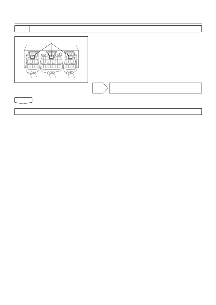
CHECK PERFORM A VISUAL CHECK OF THE DISCONNECTION DETECTION PIN
(a) Turn the ignition switch to LOCK.
Disconnection Detection Pin
(b) Disconnect the negative (-) terminal cable from the bat-
tery, and wait at least for 90 seconds.
(c)
With 3 connectors connected to the airbag sensor assy
center, place tester leads onto any 2 of 3 disconnection
detection pins and check for continuity.
OK:
Continuity
H40441
NG REPAIR OR REPLACE AIRBAG SENSOR ASSY
CENTER CONNECTOR
OK
REPLACE AIR BAG SENSOR ASSY CENTER

05-524
DIAGNOSTICS
- SUPPLEMENTAL RESTRAINT SYSTEM (April, 2003)
055Z6-04
DTC
B1140/32
SIDE AIRBAG SENSOR ASSY (RH)
MALFUNCTION
CIRCUIT DESCRIPTION
The side airbag sensor assy (RH) circuit consists of the diagnosis circuit and lateral deceleration sensor, etc.
It receives signals from the lateral deceleration sensor, judges whether or not the SRS must be activated,
and detects diagnosis system malfunction.
DTC B1140/32 is recorded when occurrence of a malfunction in the side airbag sensor assy (RH) is detected.
DTC No.
DTC Detecting Condition
Trouble Area
F Short circuit in wire harness of side airbag sensor RH
(to ground)
F Short circuit in wire harness of side airbag sensor RH
F Side airbag sensor assy (RH)
B1140/32
(to B+)
F Airbag sensor assy center
F Open circuit in wire harness of side airbag sensor RH
F Instrument panel wire No.3
F Side airbag sensor assy RH malfunction
F Airbag sensor assy center malfunction
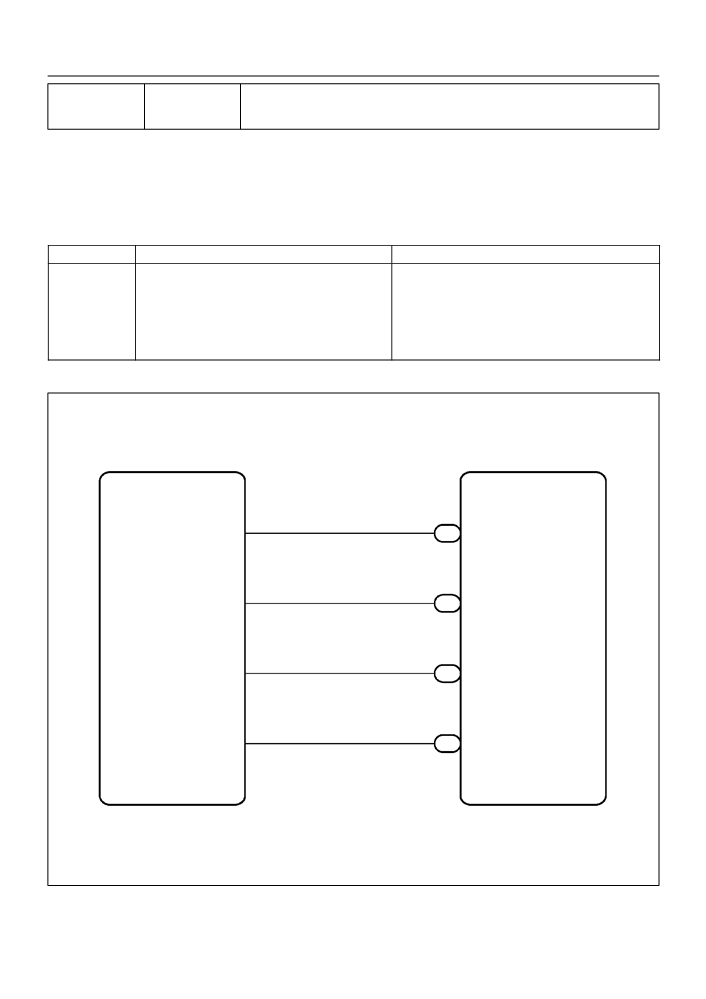
WIRING DIAGRAM
S11
Side Airbag Sensor Assy (RH)
Airbag Sensor Assy Center
7
1
GR
ESR
A14
ESR
10
2
L-Y
SSR-
A14
SSR-
9
3
LG
FSR
A14
FSR
12
4
P
VUPR
A14
VUPR
H01450
05-525
DIAGNOSTICS
- SUPPLEMENTAL RESTRAINT SYSTEM (April, 2003)
INSPECTION PROCEDURE
1
CHECK SIDE AIR BAG SENSOR ASSY RH
SST
09843-18040
(a) Connect the negative (-) terminal cable to the battery,
and wait at least for 2 seconds.
Airbag
(b) Turn the ignition switch to ON, and wait at least for 20 se-
Sensor
Side
conds.
Assy
Airbag
(c)
Clear the DTC stored in memory (See page 05-424).
Center
Sensor
(d) Turn the ignition switch to LOCK, and wait at least for 20
Assy RH
seconds.
(e) Turn the ignition switch to ON, and wait at least for 20 se-
DLC3
DTC B1140/32
conds.
(f)
Check the DTC (See page 05-424).
OK:
DTC B1140/32 is not output.
CG
Tc
HINT:
H01012
H10600
H01065
H40442
Codes other than code B1140/32 may be output at this time, but
they are not relevant to this check.
OK USE SIMULATION METHOD TO CHECK
NG
2
CHECK AIRBAG SENSOR ASSY CENTER CONNECTOR
(a) Turn the ignition switch to LOCK.
(b) Disconnect the negative (-) terminal cable from the battery, and wait at least for 90 seconds.
(c)
Check that the connectors is properly connected to the airbag sensor assy center.
NG CONNECT CONNECTORS
OK
3
CHECK SIDE AIRBAG SENSOR ASSY CONNECTOR
(a) Check that the connector is properly connected to the side airbag sensor assy (RH).
NG CONNECT CONNECTORS
OK
05-526
DIAGNOSTICS
- SUPPLEMENTAL RESTRAINT SYSTEM (April, 2003)
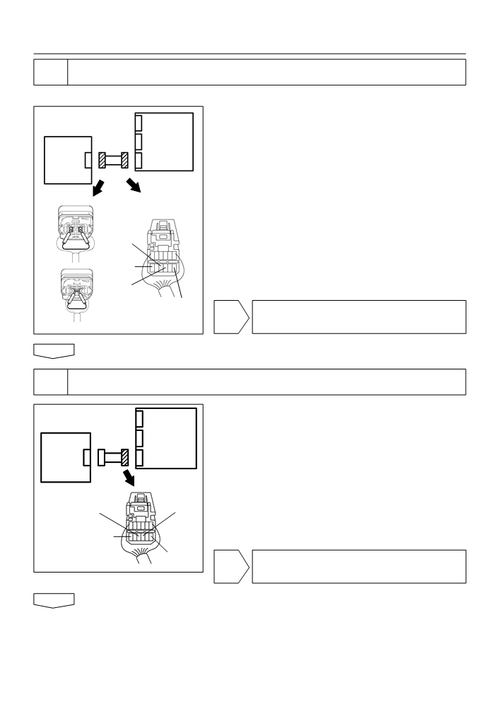
4
CHECK SIDE AIRBAG SENSOR ASSY(RH) CIRCUIT(OPEN)(AIRBAG SENSOR
ASSY CENTER - SIDE AIRBAG SENSOR ASSY RH)
SST
09843-18040
(a) Disconnect the connectors between the airbag sensor
Airbag
assy center and the side airbag sensor assy RH.
Sensor
(b) Using a service wire, connect VUPR and ESR, and FSR
Side
Assy
and SSR- of the connector (on the side airbag sensor
Airbag
Center
assy side) between the airbag sensor assy center and the
Sensor
side airbag sensor assy (RH).
Assy RH
(c)
For the connector (on the airbag sensor assy center side)
between the side airbag sensor assy RH and the airbag
sensor assy center, measure the resistance between
VUPR and ESR, and between FSR and SSR-.
OK:
SSR-
Resistance: Below 1
W
VUPR
FSR
ESR
NG REPAIR OR REPLACE INSTRUMENT PANEL
H01015
WIRE NO.3(AIRBAG SENSOR ASSY CENTER -
C91384
C91385
C82942
H41635
SIDE AIRBAG SENSOR ASSY RH)
OK
5
CHECK SIDE AIRBAG SENSOR ASSY(RH) CIRCUIT(TO GROUND)(AIRBAG
SENSOR ASSY CENTER - SIDE AIRBAG SENSOR ASSY RH)
(a) Disconnect the connection between VUPR and ESR, and
Airbag
between FSR and SSR-.
Sensor
(b) For the connector (on the airbag sensor assy center side)
Side
Assy
between the airbag sensor assy center and the side air-
Airbag
Center
bag sensor assy (RH), measure the resistance between
Sensor
each terminal of VUPR, SSR- and FSR, and body
Assy RH
ground.
OK:
FSR
Resistance: 1M W or Higher
SSR-
VUPR
ESR
NG REPAIR OR REPLACE INSTRUMENT PANEL
H01015
C82942
H40444
WIRE NO.3(AIRBAG SENSOR ASSY CENTER -
SIDE AIRBAG SENSOR ASSY RH)
OK

05-527
DIAGNOSTICS
- SUPPLEMENTAL RESTRAINT SYSTEM (April, 2003)
6
CHECK SIDE AIRBAG SENSOR ASSY(RH) CIRCUIT(AIRBAG SENSOR ASSY
CENTER - SIDE AIRBAG SENSOR ASSY RH)
(a) For the connector (on the airbag sensor assy center side)
Airbag
between the airbag sensor assy center and the side air-
Sensor
bag sensor assy (RH), measure the resistance between
Side
Assy
VUPR and ESR, and between FSR and SSR-.
Airbag
Center
OK:
Sensor
Resistance: 1M W or Higher
Assy RH
FSR
SSR-
VUPR
ESR
NG REPAIR OR REPLACE INSTRUMENT PANEL
H01015
C82942
H40444
WIRE NO.3(AIRBAG SENSOR ASSY CENTER -
SIDE AIRBAG SENSOR ASSY RH)
OK
7
CHECK SIDE AIRBAG SENSOR ASSY(RH) CIRCUIT(TO B+)(AIRBAG SENSOR
ASSY CENTER - AIDE AIRBAG SENSOR ASSY RH)
(a) Connect the negative (-) terminal cable to the battery,
Airbag
and wait at least for 2 seconds.
Sensor
(b) Turn the ignition switch to ON.
Side
Assy
(c)
For the connector (on the airbag sensor assy center side)
Airbag
Center
between the airbag sensor assy center and the side air-
Sensor
bag sensor assy (RH), measure the voltage between
Assy RH
each terminal of VUPR, SSR- and FSR, and body
ground.
FSR
OK:
SSR-
Voltage: Below 1 V
VUPR
ESR
H01015
C82942
H40444
NG REPAIR OR REPLACE INSTRUMENT PANEL
WIRE NO.3(AIRBAG SENSOR ASSY CENTER -
SIDE AIRBAG SENSOR ASSY RH)
OK

05-528
DIAGNOSTICS
- SUPPLEMENTAL RESTRAINT SYSTEM (April, 2003)
8
CHECK SIDE AIR BAG SENSOR ASSY RH
SST
09843-18040
(a) Turn the ignition switch to LOCK.
(b) Disconnect the negative (-) terminal cable from the bat-
Airbag
tery, and wait at least for 90 seconds.
Sensor
Side
Assy
(c)
Connect the airbag sensor assy center connector.
Airbag
Center
(d) Interchange the side airbag sensor assy (RH) and LH and
Sensor
connect the connectors to them.
Assy LH
(e) Connect the negative (-) terminal cable to the battery,
DTC B1140/32
and wait at least for 2 seconds.
DLC3
(f)
Turn the ignition switch to ON, and wait at least for 20 se-
conds.
DTC B1141/33
(g) Clear the DTC stored in memory (See page 05-424).
CG
(h) Turn the ignition switch to LOCK, and wait at least for 20
Tc
seconds.
H01012
H10600
H01065
H01066
H41930
(i)
Turn the ignition switch to ON, and wait at least for 20 se-
conds.
(j)
Check the DTC (See page 05-424).
OK:
(A): DTC B1140/32 is not output.
(B): DTC B1141/33 is not output.
NG(A) REPLACE AIR BAG SENSOR ASSY CENTER
NG(B) REPLACE SIDE AIR BAG SENSOR ASSY RH
OK
9
USE SIMULATION METHOD TO CHECK
NG Go to step 1
OK
REPLACE ALL SRS COMPONENTS INCLUDING THE WIRE HARNESS
05-529
DIAGNOSTICS
- SUPPLEMENTAL RESTRAINT SYSTEM (April, 2003)
055Z7-05
DTC
B1141/33
SIDE AIRBAG SENSOR ASSY (LH)
MALFUNCTION
CIRCUIT DESCRIPTION
The side airbag sensor assy (LH) circuit consists of the diagnosis circuit and lateral deceleration sensor, etc.
It receives signals from the lateral deceleration sensor, judges whether or not the SRS must be activated,
and detects diagnosis system malfunction.
DTC B1141/33 is recorded when occurrence of a malfunction in the side airbag sensor assy (LH) is detected.
DTC No.
DTC Detecting Condition
Trouble Area
F Short circuit in wire harness of side airbag sensor LH
(to ground)
F Short circuit in wire harness of side airbag sensor LH
F Side airbag sensor assy (LH)
B1141/33
(to B+)
F Airbag sensor assy center
F Open circuit in wire harness of side airbag sensor LH
F Instrument panel wire No.3
F Side airbag sensor assy LH malfunction
F Airbag sensor assy center malfunction
WIRING DIAGRAM
S10
Side Airbag Sensor Assy (LH)
Airbag Sensor Assy Center
12
1
GR-L
A12
ESL
ESL
9
2
L-W
SSL-
A12
SSL-
10
3
LG-B
FSL
A12
FSL
7
4
P-L
VUPL
A12
VUPL
H01450
05-530
DIAGNOSTICS
- SUPPLEMENTAL RESTRAINT SYSTEM (April, 2003)
INSPECTION PROCEDURE
1
CHECK SIDE AIR BAG SENSOR ASSY LH
SST
09843-18040
(a) Connect the negative (-) terminal cable to the battery,
and wait at least for 2 seconds.
Side
(b) Turn the ignition switch to ON, and wait at least for 20 se-
Airbag
Airbag
conds.
Sensor
Sensor
(c)
Clear the DTC stored in memory (See page 05-424).
Assy LH
Assy
(d) Turn the ignition switch to LOCK, and wait at least for 20
Center
seconds.
(e) Turn the ignition switch to ON, and wait at least for 20 se-
DLC3
conds.
DTC B1141/33
(f)
Check the DTC (See page 05-424).
OK:
DTC B1141/33 is not output.
CG
Tc
H01007
H10600 H01066
H40445
OK USE SIMULATION METHOD TO CHECK
NG
2
CHECK AIRBAG SENSOR ASSY CENTER CONNECTOR
(a) Turn the ignition switch to LOCK.
(b) Disconnect the negative (-) terminal cable from the battery, and wait at least for 90 seconds.
(c)
Check that the connectors is properly connected to the airbag sensor assy center.
NG CONNECT CONNECTORS
OK
3
CHECK SIDE AIRBAG SENSOR ASSY CONNECTOR
(a) Check that the connector is properly connected to the side airbag sensor assy (LH).
NG CONNECT CONNECTORS
OK

05-531
DIAGNOSTICS
- SUPPLEMENTAL RESTRAINT SYSTEM (April, 2003)
4
CHECK SIDE AIRBAG SENSOR ASSY(LH) CIRCUIT(OPEN)(AIRBAG SENSOR
ASSY CENTER - SIDE AIRBAG SENSOR ASSY LH)
SST
09843-18040
(a) Disconnect the connectors between the airbag sensor
assy center and the side airbag sensor assy LH.
Side
Airbag
(b) Using a service wire, connect VUPL and ESL, and FSL
Airbag
Sensor
and SSL- of the connector (on the side airbag sensor
Sensor
Assy LH
assy side) between the airbag sensor assy center and the
Assy
side airbag sensor assy (LH).
Center
(c)
For the connector (on the airbag sensor assy center side)
between the airbag sensor assy center and the side air-
bag sensor assy (LH), measure the resistance between
VUPL and ESL, and between FSL and SSL-.
SSL-
OK:
Resistance: Below 1
W
ESL
FSL
VUPL
NG REPAIR OR REPLACE INSTRUMENT PANEL
H01010
WIRE NO.3(AIRBAG SENSOR ASSY CENTER -
C91384
C91385
C81676
H41636
SIDE AIRBAG SENSOR ASSY LH)
OK
5
CHECK SIDE AIRBAG SENSOR ASSY(LH) CIRCUIT(TO GROUND)(AIRBAG
SENSOR ASSY CENTER - SIDE AIRBAG SENSOR ASSY LH)
(a) Disconnect the connection between VUPL and ESL, and
Side
between FSL and SSL-.
Airbag
(b) For the connector (on the airbag sensor assy center side)
Airbag
Sensor
between the airbag sensor assy center and the side air-
Assy LH
Sensor
Assy
bag sensor assy (LH), measure the resistance between
Center
each terminal of VUPL, SSL- and FSL, and body ground.
OK:
Resistance: 1M W or Higher
SSL-
ESL
H01010
FSL
VUPL
NG REPAIR OR REPLACE INSTRUMENT PANEL
C81676
H40447
WIRE NO.3(AIRBAG SENSOR ASSY CENTER -
SIDE AIRBAG SENSOR ASSY LH)
OK
Большое спасибо!
Ваше мнение очень важно для нас.
Нет комментариевНе стесняйтесь поделиться с нами вашим ценным мнением.
Текст