Toyota Corolla (2004+). Manual — part 115
71-9
INSTRUMENT PANEL/METER
- INSTRUMENT PANEL SUB-ASSY LOWER
INSTRUMENT PANEL SUB-ASSY LOWER
7108I-01
PRECAUTION
1.
PRECAUTION FOR VEHICLE WITH SRS AIRBAG AND SEAT BELT PRETENSIONER
(a) Some operations in this section may affect the SRS airbag. Before performing the corresponding op-
erations, please read the NOTICE of the SRS airbag to perform the proper operations.
71-10
INSTRUMENT PANEL/METER
- INSTRUMENT PANEL SUB-ASSY LOWER
7108J-02
REPLACEMENT
HINT:
COMPONENTS: See page 71-7
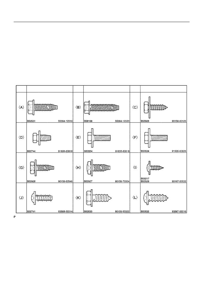
1.
TABLE OF BOLT, SCREW AND NUT
NOTICE:
Be sure to tape the tip of the screwdriver when using it to disengage the meshing of the clips and
claws.
HINT:
Indicate the bolts, screws and nuts, which are necessary for installation and removal of the instrument panel,
in the illustration and the text with alphabets.
mm (in.)
(L = Length)
Code
Shape
Code
Shape
Code
Shape
f=7
f=6
f=6
(0.28)
(0.24)
(0.24)
L=30
L=30
L=20
(1.18)
(1.18)
(0.79)
f=8
f=6
f=6
(0.32)
(0.24)
(0.24)
L=18
L=16
L=25
(0.71)
(0.63)
(0.98)
f=5
f=7
f=6
(0.20)
(0.28)
(0.24)
L=14
L=20
L=20
(0.55)
(0.79)
(0.79)
f=5
f=5
f=5
(0.20)
(0.20)
(0.20)
L=14
L=16
L=18
(0.55)
(0.63)
(0.71)
B59370
2.
PRECAUTION
3.
SEPARATE BATTERY NEGATIVE TERMINAL(See page
60-1)
4.
PLACE FRONT WHEELS FACING STRAIGHT AHEAD
5.
REMOVE HORN BUTTON ASSY(See page 60-13)
6.
REMOVE STEERING WHEEL ASSY(See page 50-8)
SST
09950-50013 (09951-05010, 09952-05010, 09953-05020, 09954-05021)
71-11
INSTRUMENT PANEL/METER
- INSTRUMENT PANEL SUB-ASSY LOWER
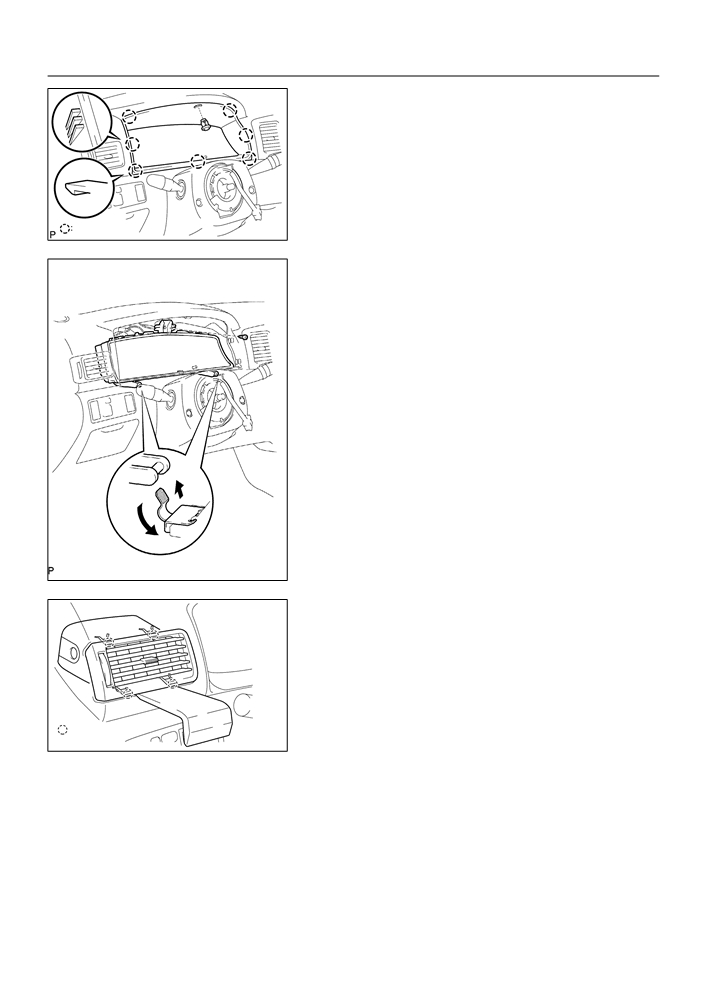
7.
REMOVE METER HOOD SUB-ASSY
(a) Remove the clip.
(b) Using a screwdriver, disengage the 7 claws, then remove
the meter hood sub-assy.
HINT:
Tape the screwdriver tip before use.
7 Claws
B59341
8.
REMOVE COMBINATION METER ASSY
(a) Remove the screw<L>.
(b) Disengage the 2 claws as shown in the illustration.
(c)
Disconnect the connector, then remove the combination
meter assy.
B59342
9.
REMOVE INSTRUMENT PANEL REGISTER ASSY
NO.1
(a) Using a moulding remover, disengage the 4 claws, then
remove the instrument panel register assy No.1.
: 4 Claws
B59344
10. REMOVE INSTRUMENT PANEL REGISTER ASSY NO.3
11. REMOVE FLOOR SHIFT SHIFT LEVER KNOB SUB-ASSY (M/T TRANSAXLE)

71-12
INSTRUMENT PANEL/METER
- INSTRUMENT PANEL SUB-ASSY LOWER
12. REMOVE CONSOLE PANEL UPPER
(a) Using a screwdriver, disengage the 6 claws.
HINT:
Tape the screwdriver tip before use.
(b) Disconnect the connector, then remove the console panel
upper.
6 Claws
B59343
13. REMOVE HEATER CONTROL KNOB
14. REMOVE INSTRUMENT CLUSTER FINISH PANEL
(a) Remove the screw<J>.
(b) Using a screwdriver, disengage the 4 clips and 4 claws,
then remove the instrument cluster finish panel.
HINT:
Tape the screwdriver tip before use.
(c)
Disconnect the connectors.
NOTICE:
Do not pull the lid of auxiliary box.
4 Clips
4 Claws
B59771
15. REMOVE INSTRUMENT CLUSTER FINISH PANEL
SUB-ASSY CENTER
(a) Remove the 4 screws<K>.
(b) Using a screwdriver, disengage the 2 clips and 4 claws,
then remove the instrument cluster finish panel sub-assy
center with radio receiver assy.
HINT:
4 Claws
Tape the screwdriver tip before use.
2 Clips
I32292
(c)
Disconnect the connectors.
16. REMOVE GLOVE COMPARTMENT DOOR ASSY
(a) Remove the screw<I> from the glove compartment door
stopper sub-assy.
(b) Deform the upper part of the glove compartment door
assy to release the stoppers.
(c)
Pull the glove compartment door assy upward to remove
it.
: Stoppers
B59350
71-13
INSTRUMENT PANEL/METER
- INSTRUMENT PANEL SUB-ASSY LOWER
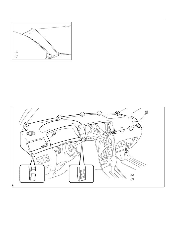
17. REMOVE FRONT PILLAR GARNISH LH
(a) Disengage the clip.
(b) Pull the front pillar garnish LH upward and disengage the
2 claws, then remove the front pillar garnish LH.
: Clip
: 2 Claws
B59351
18. REMOVE FRONT PILLAR GARNISH RH
19. SEPARATE PASSENGER AIRBAG CONNECTOR(See page 60-25)
20. REMOVE INSTRUMENT PANEL SUB-ASSY UPPER
(a) Remove the bolt<D> and 2 screws<J>.
(b) Using a moulding remover, disengage the 3 clips and 8 claws.
(c)
Remove the instrument panel sub-assy upper.
3 Clips
8 Claws
B59352
21. REMOVE HEATER CONTROL & ACCESSORY ASSY(See page 55-13)
22. REMOVE STEERING COLUMN COVER(See page 50-8)
23. REMOVE HEADLAMP DIMMER SWITCH ASSY(See page 65-23)
24. REMOVE WINDSHIELD WIPER SWITCH ASSY(See page 66-11)
71-14
INSTRUMENT PANEL/METER
- INSTRUMENT PANEL SUB-ASSY LOWER
25. REMOVE GLOVE COMPARTMENT DOOR STOPPER
SUB-ASSY
(a) Disengage the clip, then remove the glove compartment
door stopper sub-assy.
B59353
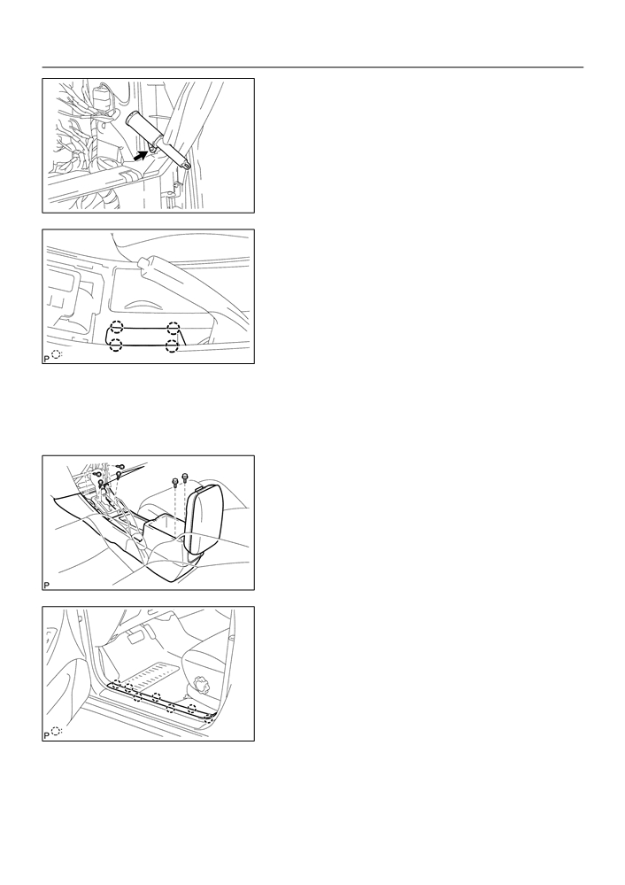
26. REMOVE PARKING BRAKE HOLE COVER
SUB-ASSY
(a) Using a screwdriver, disengage the 4 claws, then remove
the parking brake hole cover sub-assy.
HINT:
Tape the screwdriver tip before use.
4 Claws
B59354
27. REMOVE CONSOLE BOX CARPET
28. REMOVE CONSOLE BOX SUB-ASSY REAR (M/T TRANSAXLE)
29. REMOVE CONSOLE BOX SUB-ASSY REAR
A/T Only:
(a) A/T Transaxle:
Remove the 2 bolts<F>, 4 screws<J> and console box
sub-assy rear.
(b) M/T Transaxle:
Remove the 2 bolts<F>, 2 screws<J> and console box
sub-assy rear.
B59355
30. REMOVE FRONT DOOR SCUFF PLATE LH
(a) Using a screwdriver, disengage the 7 claws, then remove
the front door scuff plate LH.
HINT:
Tape the screwdriver tip before use.
7 Claws
B59356
31. REMOVE FRONT DOOR SCUFF PLATE RH

71-15
INSTRUMENT PANEL/METER
- INSTRUMENT PANEL SUB-ASSY LOWER
32. REMOVE COWL SIDE TRIM BOARD LH
(a) Remove the clip.
(b) Disengage the clip, then remove the cowl side trim board
LH.
: Clip
B59357
33. REMOVE COWL SIDE TRIM BOARD RH
34. REMOVE INSTRUMENT PANEL SUB-ASSY LOWER
(a) Disconnect the DLC3 connector.
(b) Remove the hood lock control lever.
(c)
Remove the 3 screws<G> or <H>.
(d) Remove the 2 bolts<E>.
(e) Remove the bolt<A> or <B>.
(f)
Remove the bolt<C>.
(g) Remove the 8 clips and instrument panel sub-assy lower.
<G> or <H>
<G> or <H>
<G> or <H>
<E>
<A> or <B>
<C>
<E>
B59358
35. REMOVE INSTRUMENT PANEL BOX
36. REMOVE INSTRUMENT PANEL BOX SPRING
37. INSTALL HEATER CONTROL & ACCESSORY ASSY(See page
55-13)
71-16
INSTRUMENT PANEL/METER
- INSTRUMENT PANEL SUB-ASSY LOWER
38. INSTALL INSTRUMENT PANEL SUB-ASSY UPPER
(a) Install the instrument panel sub-assy upper.
(b) Install the bolt<D> and 2 screws<J>.
Torque:
Bolt <D>: 20 N m (204 kgf cm, 15 ft lbf)
39. INSTALL INSTRUMENT CLUSTER FINISH PANEL SUB-ASSY CENTER
40. CENTER SPIRAL CABLE(See page 60-22)
41. INSTALL STEERING WHEEL ASSY(See page 50-8)
42. INSPECT STEERING WHEEL CENTER POINT
43. INSPECT HORN BUTTON ASSY(See page 60-13)
44. INSTALL HORN BUTTON ASSY(See page 60-13)
45. INSPECT SRS WARNING LIGHT

71-2
INSTRUMENT PANEL/METER
- COMBINATION METER
7108O-01
ON-VEHICLE INSPECTION
1.
INSPECT SPEEDOMETER
(a) Check the operation.
(1)
Using a speedometer tester, inspect the speedometer fro allowable indication error and check
the operation of the odometer.
Reference:
USA (mph)
CANADA (km/h)
Standard indication
Allowable range
Standard indication
Allowable range
20
19 - 22
20
18 - 23
40
39 - 42.5
40
40 - 44
60
59 - 63
60
60 - 64.5
80
79 - 83.5
80
80 - 85
100
99 - 104
100
100 - 105
–
-
120
120 - 125.5
–
-
140
140 - 146
–
-
160
160 - 167
NOTICE:
Tire wear and tire over or under inflation will increase the indication error.
(2)
Check the deflection width of the speed meter indicator.
Reference: Below 0.5 km/h / 0.3 mph
2.
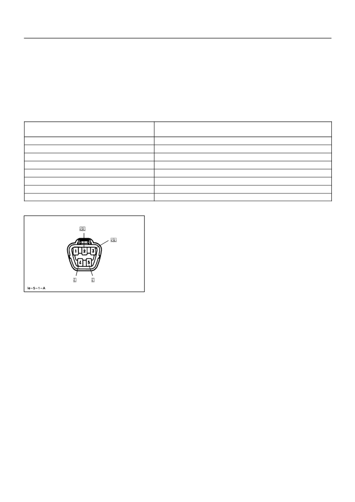
INSPECT OUTPUT SIGNAL OF VEHICLE SPEED
(a) Check for standard signal.
(1)
While driving the vehicle at the speed of 10 km/h,
check the voltage between the terminals C9-10
and C9-1 of the combination meter assy.
Standard: Fluctuation between 10 to 14 V or less is re-
peated 7 times within 1 sec.
C9-1
C9-10
NOTICE:
I32114
Check it with the ignition switch ON and the connector con-
nected.
71-3
INSTRUMENT PANEL/METER
- COMBINATION METER
3.
INSPECT TACHOMETER
(a) Check the operation
(1)
Connect a tune-up test tachometer, and start the engine.
NOTICE:
F
Reversing the connection of the tachometer will damage the transistors and diodes inside.
F
When removing or installing the tachometer, be careful not to drop or subject it to heavy
shocks.
(2)
Compare the test and tachometer indications.
DC 13.5 V, 25 _C at (77 _F)
Allowable range (r/min)
Standard indication (r/min)
Data in (
) are for reference
700
630 - 770
1,000
(900 - 1,100)
2,000
(1,850 - 2,150)
3,000
2,800 - 3,200
4,000
(3,800 - 4,200)
5,000
4,800 - 5,200
6,000
(5,750 - 6,250)
7,000
6,700 - 7,300
4.
INSPECT FUEL RECEIVER GAUGE
(a)
Inspect the circuit.
(1)
Disconnect the connector from the sender gauge.
(2)
Turn the ignition switch ON, then check the position
of the receiver gauge needle.
Needle position: EMPTY
(3)
Connect terminals 2 and 3 on the wire harness side
connector and Turn the ignition switch ON, then
H40110
check the position of the receiver gauge needle.
Needle position: FULL
5.
INSPECT FUEL LEVEL WARNING
(a)
Inspect the circuit.
(1)
Disconnect the connector from the sender gauge.
(2)
Turn the ignition switch ON, check the fuel level needle indicates EMPTY and fuel level warning
lights light on.
6.
INSPECT WATER TEMPERATURE RECEIVER GAUGE WARNING LIGHT
(a)
Inspect the circuit.
(1)
Disconnect the connector from the sender gauge.
(2)
Turn the ignition switch ON, check the position of the water temperature receiver gauge needle.
Needle position: COOL
(3)
Connect between terminals on the wire harness side connector, then check the position of the
water temperature receiver gauge needle.
Needle position: HOT
71-4
INSTRUMENT PANEL/METER
- COMBINATION METER
7.
INSPECT LOW OIL PRESSURE WARNING LIGHT
(a)
Inspect the circuit.
(1)
Disconnect the connector from the low oil pressure switch.
(2)
Turn the ignition switch ON.
(3)
Connect the terminal of wire harness side connector and ground, then check the warning low
oil pressure warning light.
Low oil pressure warning light: Light on
8.
INSPECT LOW OIL PRESSURE SWITCH
(a)
Check the continuity.
(1)
Disconnect the connector from the low oil pressure switch.
(2)
Check that continuity exists between terminal and ground.
Engine stopped: continuity
Engine running: no continuity
9.
INSPECT BRAKE WARNING LIGHT
(a)
Inspect the parking brake warning light.
(1)
Disconnect the connector from the parking brake switch and ground terminal on the wire harness
side connector.
(2)
Turn the ignition switch ON and check that the warning light lights up.
(b)
Inspect the brake fluid level warning light.
(1)
Disconnect the connector from the brake fluid level warning switch and connect terminals on the
wire harness side connector.
(2)
Turn the ignition switch ON and check that the warning light lights up.
10.
INSPECT BRAKE FLUID LEVEL WARNING SWITCH
(a)
Inspect the continuity.
(1)
Remove the reservoir tank cap and strainer.
(2)
Disconnect the connector.
(3)
Check that the continuity exists between the terminals.
Float up (switch off): No continuity
(4)
Use syphon, etc., to take fluid out of the reservoir tank.
(5)
Check that the continuity exists between the terminals.
Float down (switch on): Continuity
(6)
Pour the fluid back in the reservoir tank.
71-5
INSTRUMENT PANEL/METER
- COMBINATION METER
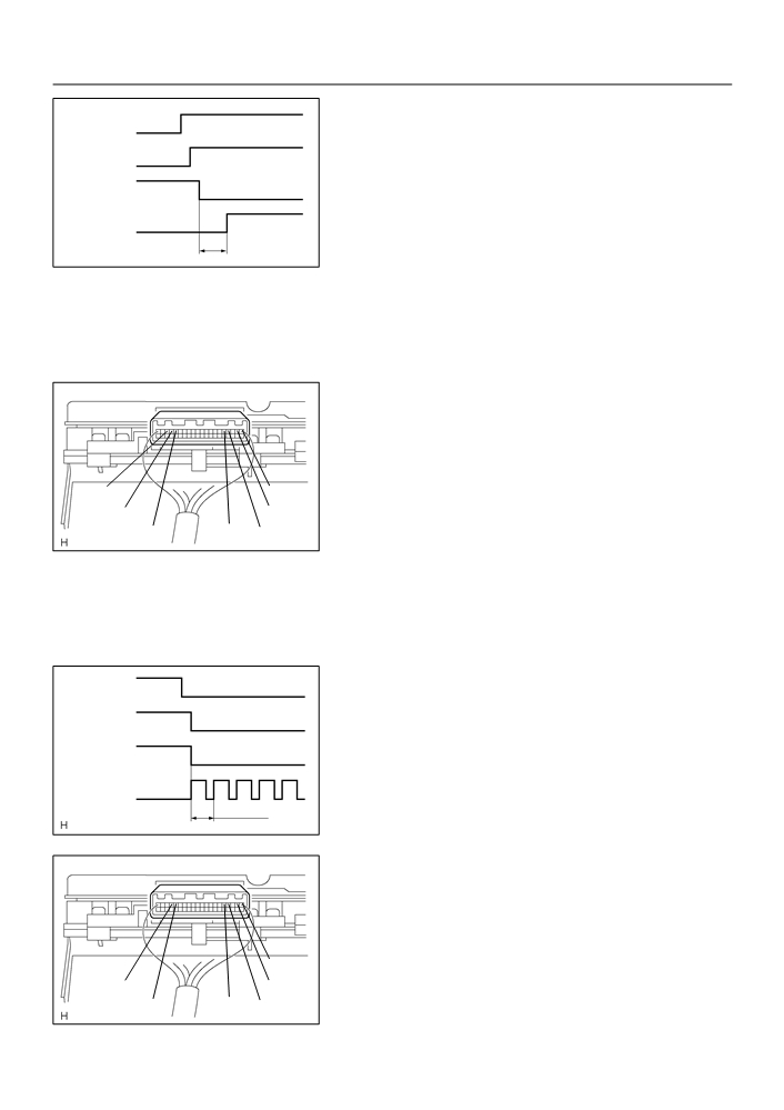
11. INSPECT LIGHT AUTO TURN OFF BUZZER
ON
(a) Check the operation.
Light Switch
OFF
HINT:
Key Unlock
OFF
Warning Switch
ON
When the key unlock warning and light auto turn off warning is
output simultaneously, the key unlock warning precedes the
Courtesy Switch
OFF
ON
(Driver’s side)
other.
ON
(1)
Remove the ignition key with the tail light switch ON
Buzzer
and the driver side door open and check for the
0.2S
I32305
buzzer.
Buzzer sound: Continuous
(2)
While the buzzer is sounding, perform any of the fol-
lowing and check that the buzzer sound is stopped.
F
Turn the tail light switch OFF.
F
Close the driver side door.
F
Insert the ignition key into the key cylinder.
(b) Check the function.
(1)
Remove the combination meter.
(2)
Connect the position (+) lead from battery to termi-
nal C9-5 and negative (-) lead to terminal C9-1
and C9-2.
(3)
Connect the position (+) lead from battery to termi-
C9-18
C9-1
nal C9-18 and negative (-) lead to terminal C9-16
C9-17
C9-2
and C9-17, check that the buzzer sound.
C9-16
C9-5
C9-4
H40113
Buzzer sound: Continuous
(4)
While the buzzer is sounding, connect the battery
positive terminal to terminal C9-4 and check that
the buzzer sound is stopped.
12. INSPECT KEY UNLOCK WARNING BUZZER
Key Unlock
OFF
ON
Warning Switch
(a) Check the operation.
HINT:
IG Switch
ON
OFF(LOCK,ACC)
When the key unlock warning and light auto turn off warning is
Courtesy Switch
output simultaneously, the key unlock warning precedes the
OFF
(Driver’s side)
ON
other.
ON ON ON ON ON
(1)
While the driver side door is open, insert the ignition
Buzzer
0.5S
0.2S
key, set the ignition switch to OFF (LOCK or ACC)
I32306
and check for the buzzer sound.
Buzzer sound: Intermittent
(b) Check the function.
(1)
Remove the combination meter.
(2)
Connect the position (+) lead from battery to termi-
nal C9-5 and negative (-) lead to terminal C9-1
and C9-2.
(3)
Connect the negative (-) lead to terminal C9-16
C9-1
and C9-17, check that the buzzer sound.
C9-17
C9-2
Buzzer sound: Intermittent
C9-5
C9-4
C9-16
H40113
71-6
INSTRUMENT PANEL/METER
- COMBINATION METER
(4)
While the buzzer is sounding, connect the battery
positive terminal to terminal C9-4 and check that
the buzzer sound is stopped.

71-1
INSTRUMENT PANEL/METER
- COMBINATION METER
COMBINATION METER
7108N-03
PROBLEM SYMPTOMS TABLE
Warning Lights:
Symptom
Suspect Area
See page
1.
Wire Harness or Connector
-
Check Engine warning light does not light up.
2.
ECM
05-1
3.
Combination Meter Assy
-
1.
Wire Harness or Connector
-
Discharge warning light does not light up.
2.
ECM
05-1
3.
Combination Meter Assy
-
1.
Wire Harness or Connector
-
Brake warning light does not light up.
2.
Brake Actuator Assy
05-294
3.
Combination Meter Assy
-
1.
Wire Harness or Connector
-
ABS warning light does not light up.
2.
Brake Actuator Assy
05-294
3.
Combination Meter Assy
-
1.
Wire Harness or Connector
-
SRS warning light does not light up.
2.
Airbag Sensor Assy Center
05-421
3.
Combination Meter Assy
-
1.
Wire Harness or Connector
-
Open Door warning light does not light up.
2.
Courtesy Lamp Switch
65-7
3.
Combination Meter Assy
-
1.
Wire Harness or Connector
-
Fuel Level warning light does not light up.
2.
Fuel Sender Gage Assy
05-655
3.
Combination Meter Assy
-
1.
Wire Harness or Connector
-
Low Oil Pressure warning light does not light up.
2.
Oil Pressure Switch Assy
71-2
3.
Combination Meter Assy
-
1.
Wire Harness or Connector
-
Window washer level warning does not lights up
2.
Window washer level waring switch
-
3.
Combination Meter Assy
-
1.
Driver Seat Belt Buckle Switch
05-661
Driver seat belt warning buzzer does not sound.
2.
Wire Harness or Connector
-
3.
Combination Meter Assy
-
1.
Front Seat Inner Belt Assy
05-663
2.
Separate Type Front Seat Cushion Pad
05-663
Seat belt warning lamp for front passenger seat does not flash.
3.
Combination Meter Assy
-
4.
Passenger Seat Belt Warning Light Assy
-
Indicator Lights:
Symptom
Suspect Area
See page
1.
Wire Harness or Connector
-
Turn indicator light does not light up.
2.
Turn Signal and Hazard Warning System
65-7
3.
Combination Meter Assy
-
1.
Wire Harness or Connector
-
High Beam indicator light does not light up.
2.
Headlight Dimmer Switch
65-7
3.
Combination Meter Assy
-
1.
Wire Harness or Connector
-
2.
O/D Main Switch Circuit
05-417
O/D OFF indicator light does not light up.
3.
ECM
-
4.
Combination Meter Assy
-
72-1
SEAT
- FRONT SEAT
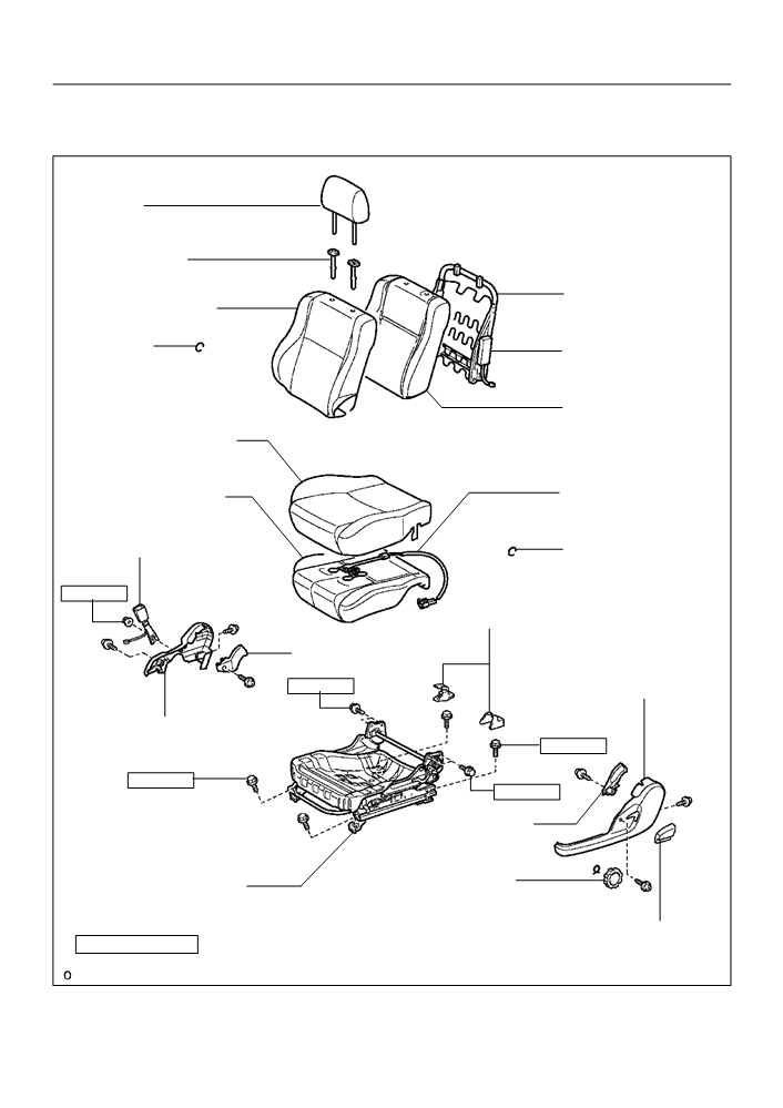
FRONT SEAT
7209X-01
COMPONENTS
Headrest
Headrest Support
Front Seat Back
Spring Assy
Front Seat Back Cover
F Hog Ring
w/ Side Airbag:
Side Airbag
Front Seat Back Pad
Front Seat Cushion Cover
Passenger Seat:
Belt Warning Occupant
Front Seat Cushion Pad
Detection Sensor
Front Seat Belt Inner
F Hog Ring
42 (430, 31)
Seat Track Cover
Reclining Adjuster
Inside Cover
Front Seat Cushion
43 (440, 32)
Shield Outer
Front Seat Cushion
Shield Inner
47 (480, 35)
47 (480, 35)
43 (440, 32)
Reclining Adjuster
Inside Cover
Vertical Seat
Front Seat Adjuster
Adjuster Knob
Reclining Adjuster
Nm (kgfcm, ftlbf)
: Specified torque
Release Handle
F Non-reusable part
B52074
Большое спасибо!
Ваше мнение очень важно для нас.
Нет комментариевНе стесняйтесь поделиться с нами вашим ценным мнением.
Текст