Toyota Corolla (2004+). Manual — part 51
05-671
DIAGNOSTICS
- POWER DOOR LOCK CONTROL SYSTEM
057TE-01
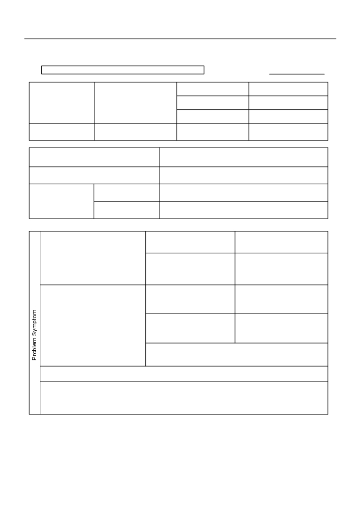
CUSTOMER PROBLEM ANALYSIS CHECK
POWER DOOR LOCK CONTROL SYSTEM Check Sheet
Inspector’s name:
Registration No.
Customer’s Name
Registration Year
Frame No.
Date Vehicle
km
/
/
Odometer Reading
Brought in
Mile
Date Problem First Occurred
/
/
F Constant F Sometimes ( Times per day, month)
Frequency Problem Occurs
F Once only
F Fine
F Cloudy
F Rainy
F Snowy
Weather
Weather Conditions
F Various/Others
When Problem
F Hot F Warm
F Cool
Occurred
Outdoor temperature
F Cold (Approx.
F (
C))
F Malfunction in Door
F Driver’s side door lock
F Driver’s side door
Lock/Unlock Operation
control switch.
F Passenger’s side door
Using Door Lock Control
Switch.
F Passenger’s side door
F Driver’s side door
lock control switch.
F Passenger’s side door
F Malfunction in Door
F Driver’s side door key
F Driver’s side door
Lock/Unlock Operation
lock and unlock control
F Passenger’s side door
Using Key.
switch.
F Passenger’s side door
F Driver’s side door
key lock and unlock control
F Passenger’s side door
switch.
F 2-step unlocking function of driver’s side door key lock
and unlock switch.
F Malfunction in Key Confinement Prevention Function.
F Others.
05-672
DIAGNOSTICS
- POWER DOOR LOCK CONTROL SYSTEM
057TF-01
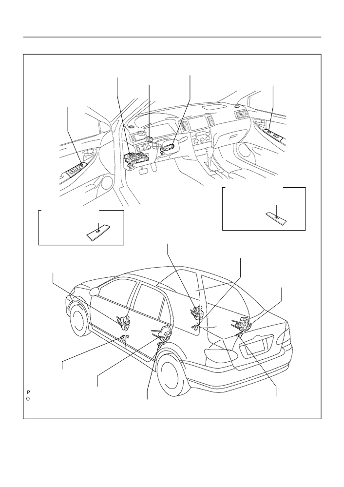
LOCATION
Un-lock Warning
Instrument Panel J/B
Switch Assy
(Integration Relay)
w/ Power Window:
w/ Power Window:
Center J/B
Door Lock Control Switch
Power Window Regulator
Master Switch Assy
(Door Lock Control Switch)
w/o Power Window
Door Lock Control Switch Assy
(Passenger’s Side)
w/o Power Window
Door Lock Control Switch Assy
(Driver’s Side)
Front Door Lock Assy RH
Front Door Courtesy
Lamp Switch Assy
Front Door Lock Assy LH
Rear Door Lock Assy RH
Front Door Courtesy
Lamp Switch Assy
Rear Door Lock Assy LH
Rear Door Courtesy
Rear Door Courtesy
B59155
B59883
Lamp Switch Assy
Lamp Switch Assy
B59152
B59531

05-676
DIAGNOSTICS
- POWER DOOR LOCK CONTROL SYSTEM
057TH-01
PROBLEM SYMPTOMS TABLE
Symptom
Suspected Area
See page
1. Door lock control switch
All doors are not operated by driver’s door key cylinder
2. Front door lock assy LH
05-677
interlocked with key
3. Wire harness
4. Integration relay
1. Un-lock warning switch assy
Key confinement prevention function does not work properly
2. Front door courtesy lamp switch assy
05-682
(Unlock warning switch circuit)
3. Wire harness
4. Integration relay
05-673
DIAGNOSTICS
- POWER DOOR LOCK CONTROL SYSTEM
057TG-01
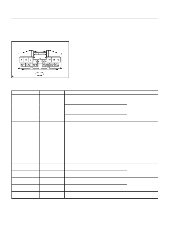
TERMINALS OF ECU
1.
INSPECT INTEGRATION RELAY
Integration Relay Connector
(Wire Harness Side)
I11
B57790
(a) Disconnect the connector and check the continuity of each terminal of the disconnected connector.
Standard :
Symbols (Terminal No.)
Wiring color
Condition
Specified Condition
[w/ power window]
Master switch (Manual door lock operation)
OFF LOCK
L1 (I11-9)
[w/o power window]
L-W Body ground
No continuity Continuity
Body ground
Driver’s door control switch (Manual operation)
OFF LOCK
Passenger’s door control switch (Manual operation)
OFF LOCK
Key in driver’s door lock cylinder
L2 (I11-7)
LOCK Other position
G Body ground
Continuity No continuity
Body ground
Key in passenger’s door lock cylinder
LOCK Other position
[w/ power window]
Master switch (Manual door lock operation)
OFF UNLOCK
UL1 (I11-8)
[w/o power window]
L Body ground
No continuity Continuity
Body ground
Door control switch (Manual operation)
OFF UNLOCK
Passenger’s door control switch (Manual operation)
OFF UNLOCK
UL2 (I11-5)
Key in passenger’s door lock cylinder
L-B Body ground
Body ground
UNLOCK Other position
Continuity No continuity
UL3 (I11-6)
Key in driver’s door lock cylinder
L-Y Body ground
Body ground
UNLOCK Other position
LSWD (I11-19)
Driver’s door lock control knob
W Body ground
Body ground
LOCK UNLOCK
No continuity Continuity
LSWP (I11-18)
Passenger’s door lock control knob
W-R Body ground
Body ground
LOCK UNLOCK
PCTY (I11-13)
R-W Body ground
Passenger’s door fully closed Opened
No continuity Continuity
Body ground
If the result is not as specified, the vehicle’s side may malfunction.

05-674
DIAGNOSTICS
- POWER DOOR LOCK CONTROL SYSTEM
(b) Reconnect the connector and check each terminal.
Standard:
Symbols (Terminal No.)
Wiring color
Condition
Specified Condition
ACTD (I11-1)
Key in driver’s door lock cylinder
0 V 10 - 14 V
R Body ground
Body ground
OFF LOCK
1 V or less
If the result is not as specified, the integration relay may malfunction.
2.
INSPECT INSTRUMENT PANEL J/B (INTEGRATION RELAY)
Instrument Panel J/B (Integration Relay)
Instrument Panel J/B Side
ID
IK
Connector IA
IA
IB
Instrument Panel J/B Side
Connector IB
IF
IH
IJ
Instrument Panel J/B Side
Instrument Panel J/B Side
Instrument Panel J/B Side
Connector IK
Connector IF
Connector IJ
Instrument Panel J/B Side
Instrument Panel J/B Side
Connector IH
Connector ID
B59376
B59378
B59532

05-675
-
DIAGNOSTICS
POWER DOOR LOCK CONTROL SYSTEM
(a) Inspect the DOOR fuse.
(b) Disconnect connectors ID, IF, IH and IJ of the instrument panel J/B.
(c)
Check each terminal of the disconnected connectors.
Standard:
Symbols (Terminal No.)
Wiring color
Condition
Specified Condition
KSW (IJ-8)
L-B Body ground
No key in ignition switch lock cylinder Inserted
No continuity Continuity
Body ground
GND (IF-4)
W-B Body ground
Body ground
Constant
Continuity
GND (IH-10)
W-B Body ground
Body ground
DCTY (ID-1)
R-W Body ground
Driver’s door fully closed Opened
Body ground
PRCTY (ID-14)
R-B Body ground
Rear LH door fully closed Opened
No continuity Continuity
Body ground
PRCTY (ID-15)
R-Y Body ground
Rear RH door fully closed Opened
Body ground
If the result is not as specified, the vehicle’s side may malfunction.
(d) Reconnect the connectors and check each terminal.
Standard:
Symbols (Terminal No.)
Wiring color
Condition
Specified Condition
IG (IA-1) Body ground
W Body ground
Constant
10
- 14 V
+B (IB-1) Body ground
W Body ground
KSW (IJ-8)
L-B Body ground
No key in ignition switch lock cylinder Inserted
10 - 14 V 0 V
Body ground
ACT+ (IK-2)
Key in driver’s door lock cylinder
L Body ground
Body ground
OFF LOCK
ACT+ (ID-9)
Key in driver’s door lock cylinder
L Body ground
Body ground
OFF UNLOCK
0 V 10 - 14 V
ACT- (IK-5)
Key in driver’s door lock cylinder
1 V or less
R Body ground
Body ground
OFF LOCK
ACT- (ID-20)
Key in driver’s door lock cylinder
R Body ground
Body ground
OFF UNLOCK
If the result is not as specified, the instrument panel J/B (integration relay) assembly may malfunction.
05-670
DIAGNOSTICS
- POWER DOOR LOCK CONTROL SYSTEM
POWER DOOR LOCK CONTROL SYSTEM
057TD-01
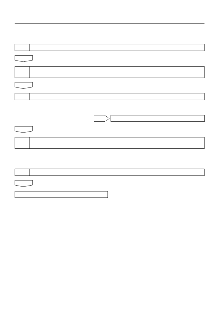
HOW TO PROCEED WITH TROUBLESHOOTING
1
VEHICLE BROUGHT IN
2
CUSTOMER PROBLEM ANALYSIS CHECK AND SYMPTOM CHECK
(See page 05-671)
3
PROBLEM SYMPTOMS TABLE (See page 05-676)
(a) Without applicable symptoms, proceed to ”A”
(b) With applicable symptoms, proceed to ”B”
B
GO TO STEP 5
A
4
PERFORM TROUBLESHOOTING IN THE FOLLOWING METHOD, DEPENDING ON
MALFUNCTION SYMPTOM
(a) Terminals of ECU (See page 05-673)
(b) Inspection (See page 73-3)
(c)
On-vehicle inspection (See page 73-1)
5
ADJUSTMENT, REPAIR OR REPLACEMENT
END
05-682
DIAGNOSTICS
- POWER DOOR LOCK CONTROL SYSTEM
057TJ-01
KEY CONFINEMENT PREVENTION FUNCTION DOES NOT WORK
PROPERLY (UNLOCK WARNING SWITCH CIRCUIT)
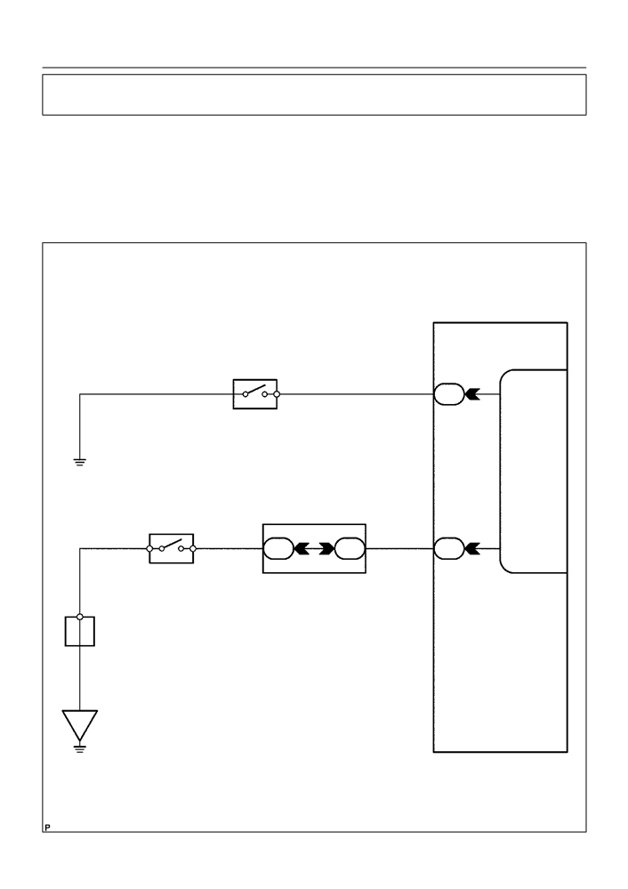
CIRCUIT DESCRIPTION
The unlock warning switch turns on when the key is inserted in the ignition key cylinder and the door courtesy
switch turns on when the driver’s door is opened, and the integration relay monitors both switches conditions.
According to these switches conditions, the integration relay controls the door locking operation not to lock
the doors while both switches are on, in order to prevent the key from being confined.
WIRING DIAGRAM
Instrument Panel J/B
D4
I11
Front Door Courtesy Lamp Switch Assy
Integration Relay
(Driver’s Side)
1
1
R-W
5
ID
DCTY
U1
Center J/B
Un-lock Warning Switch Assy
15
16
8
W-B
1
2
L-B
L-B
4
*1
4A
4A
IJ
KSW
A
J6
J/C
*1: w/ Door Lock Control
IE
B59535
05-683
DIAGNOSTICS
- POWER DOOR LOCK CONTROL SYSTEM
INSPECTION PROCEDURE
1
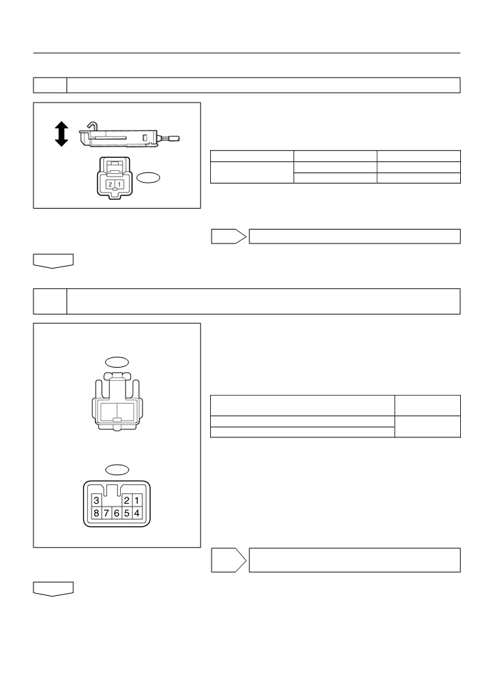
INSPECT UN-LOCK WARNING SWITCH ASSY
(a) Remove the un-lock warning switch assy.
Free Un-lock Warning Switch Assy
(b) Inspect the un-lock warning switch assy continuity, as
shown in the illustration and table.
Standard:
Push
Terminal No.
Condition
Specified condition
Free
No continuity
U1-1 U1-2
U1
Push
Continuity
B51903
NG REPLACE UN-LOCK WARNING SWITCH ASSY
OK
2
CHECK WIRE HARNESS
(UN-LOCK WARNING SWITCH INSTRUMENT PANEL J/B)
(a) Disconnect the un-lock warning switch assy and instru-
Un-lock Warning Switch Assy
ment panel J/B connectors.
(Wire Harness Side)
(b) Check the continuity between the terminals of the un-lock
U1
warning switch assy and instrument panel J/B connec-
tors, as shown in the illustration and table.
Standard (Check for open):
Symbols (Terminal No.)
Specified condition
1
2
(Un-lock warning switch Instrument panel J/B)
(U1-2) KSW (IJ-8)
Continuity
(U1-1) Body ground
Instrument Panel J/B
(Wire Harness Side)
IJ
B59536
NG REPAIR OR REPLACE WIRE HARNESS AND
CONNECTOR
OK

05-684
DIAGNOSTICS
- POWER DOOR LOCK CONTROL SYSTEM
3
INSPECT FRONT DOOR COURTESY LAMP SWITCH ASSY (DRIVER’S SIDE)
Front Door Courtesy Lamp Switch Assy
(a) Remove the courtesy lamp switch.
(Driver’s Side)
(b) Inspect the courtesy lamp switch continuity, as shown in
Free
D4
the illustration and table.
Push
Standard:
Terminal No.
Condition
Specified condition
Free
Continuity
D4-1 Body ground
Push
No continuity
B58556
NG REPLACE FRONT DOOR COURTESY LAMP
SWITCH ASSY
OK
4
CHECK WIRE HARNESS
(FRONT DOOR COURTESY LAMP SWITCH ASSY [DRIVER’S SIDE]
INSTRUMENT PANEL J/B)
(a) Disconnect the courtesy lamp switch and instrument pan-
Front Door Courtesy Lamp Switch Assy
el J/B connectors.
[Driver’s Side] (Wire Harness Side)
(b) Check the continuity between the terminals of the courte-
D4
sy lamp switch and instrument panel J/B connectors, as
shown in the illustration and table.
Standard (Check for open):
Symbols (Terminal No.)
1
Specified condition
(Courtesy lamp switch Instrument panel J/B)
(D4-1) DCTY (ID-1)
Continuity
Instrument Panel J/B
(Wire Harness Side)
ID
NG REPAIR OR REPLACE WIRE HARNESS AND
B59537
CONNECTOR
OK
REPLACE INTEGRATION RELAY
05-41
DIAGNOSTICS
- SFI SYSTEM (April, 2003)
05CRM-02
CHECK FOR INTERMITTENT PROBLEMS
Hand-held tester only:
By putting the vehicle’s ECM in the check mode, the 1 trip detection logic is possible instead of the
2 trip detection logic, and the sensitivity to detect faults is increased. This makes it easier to detect
intermittent problems.
(a) Clear the DTCs (See page 05-11).
(b) Set the check mode (See page 05-11).
(c)
Perform a simulation test (See page 01-20).
(d) Check the connector and terminal (See page 01-30).
(e) Wiggle the harness and connector (See page 01-30).
05-11
DIAGNOSTICS
- SFI SYSTEM (April, 2003)
05CRI-02
CHECK MODE PROCEDURE
HINT:
Hand-held tester only:
Compared to the normal mode, the check mode has more sens-
ing ability to detect malfunctions. Furthermore, the same diag-
nostic items which are detected in the normal mode can also be
detected in the check mode.
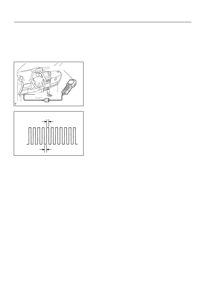
1.
CHECK MODE PROCEDURE(Using the hand-held
Hand-held Tester
tester)
(a) Check the initial conditions.
(1)
Battery positive voltage 11 V or more
(2)
Throttle valve fully closed
(3)
Transmission in the P or N position
(4)
A/C switched OFF
DLC3
(b) Turn the ignition switch OFF.
A79121
(c)
Connect the hand-held tester to the DLC3.
(d) Turn the ignition switch ON.
(e) Switch the hand-held tester from the normal mode to the
check mode (check that the MIL flashes).
0.13 sec.
NOTICE:
ON
If the hand-held tester switches the ECM from the normal
mode to the check mode or vice-versa, or if the ignition
switch is turned from ON to ACC or OFF during the check
OFF
mode, the DTC and freeze frame data will be erased.
(f)
Start the engine (MIL goes off after the engine starts).
0.13 sec.
A76900
(g) Simulate the conditions of the malfunction described by
the customer.
NOTICE:
Leave the ignition switch ON until you have checked the
DTC, etc.
(h) After simulating the malfunction conditions, check the
DTC and freeze frame data, etc using the hand-held tes-
ter diagnosis selector.
HINT:
Do not turn the ignition switch OFF, as turning it OFF switches
the diagnosis system from the check mode to the normal mode,
which erases all the DTCs, etc.
(i)
After checking the DTC, inspect the applicable circuit.
2.
CLEAR DTC (Using the OBD II scan tool or hand-held
tester)
(a) Connect the OBD II scan tool or hand-held tester to the
DLC3.
(b) Turn the ignition switch ON.
(c)
Operate the OBD II scan tool or hand-held tester to erase
the codes. All the DTCs and freeze frame data will be
erased. (See the OBD II scan tool’s manual book for
operating manuals.)
05-12
DIAGNOSTICS
- SFI SYSTEM (April, 2003)
3.
CLEAR DTC (Not using the OBD II scan tool or hand-
held tester)
(a) Disconnect the battery terminal or remove the EFI fuse
from the engine room R/B for more than 60 seconds.
05-27
DIAGNOSTICS
- SFI SYSTEM (April, 2003)
05DIG-01
CHECKING MONITOR STATUS
HINT:
”MONITOR RESULT” indicates normal or malfunction of each
component and system when judgment has done.
1.
HOW TO READ DATA
MONITOR RESULT
(a) Connect the hand-held tester to the DLC 3.
CATALYST#1 B1 . INCMP
(b) Enter ”MONITOR RESULT” from ”DIAGNOSIS / EN-
CATALYST#1 B2 . INCMP
O2S HEAT B1S1 . INCMP
HANCED OBD II / MONITOR INFO / MONITOR RESULT”
O2S HEAT B1S2 . INCMP
on the hand-held tester. You will see ”Test ID” and
O2S HEAT B2S1 . INCMP
”INCMP”, ”Pass” or ”Fail” on the MONITOR RESULT
O2S HEAT B2S2 . INCMP
THERMOSTAT
PASS
screen.
Press [ENTER] to
HINT:
Select the Label .
A82674
F
INCMP: The judgement has not been done yet.
F
PASS: Normal is detected.
F
FAIL: Malfunction is detected.
(c)
Select a Test ID that you want from the list and press the
Thermostat malfunction
”ENTER” button. You will see the following screen:
VAL
119.375_C
(1)
VAL (TEST VALUE)
[Test Data] [Unit]
LMT
75.000_C
(2)
LMT (TEST LIMIT)
[Test Limit] [Unit]
TLT
1
(3)
TLT
[Test Limit Type]
[HELP] to notice
[EXIT] to return
A82675
(d) By pressing the ”HELP” button, you can see more in-
When TEST is PASS,
formation.
TLT =
0
VALUE < LIMIT
HINT:
TLT =
1
VALUE > LIMIT
F
Monitor test results can be viewed in the MONITOR RE-
SULT screen.
When TEST is FAIL,
TLT =
0
F
Monitor test results indicate the latest malfunction judge-
VALUE > LIMIT
TLT =
1
ment result of this diagnostic.
VALUE < LIMIT
F
TEST VALUE indicates the detection parameter value
[EXIT] to return
A82676
(Example: P0128 Thermostat Malfunction = Engine cool-
ant temperature) at the time of malfunction (or normal)
judgement is done.
F
TEST LIMIT indicates a threshold of malfunction judge-
ment (Example: P0128 Thermostat Malfunction = 75_C).
F
When the monitor runs, the monitored Parameter’s VAL-
UE is recorded. The value is then compared to the TEST
LIMIT to determine if the result is PASS or FAIL.
F
By comparing the Parameter VALUE to the TEST LIMIT,
it is possible to determine the degree of failure.
05-28
DIAGNOSTICS
- SFI SYSTEM (April, 2003)
F
In rare cases, the monitor may have passed even with a
DTC set and MIL illuminated. The monitor may have
failed on a previous trip, and then passed on the most re-
cent trip. This would indicated an intermittent problem
may be the cause of the DTC.
Большое спасибо!
Ваше мнение очень важно для нас.
Нет комментариевНе стесняйтесь поделиться с нами вашим ценным мнением.
Текст