Lexus ES300 (2002 year). Service manual — part 206
To Ignition SW
IG Terminal
Fuse
Relay
SW2
Solenoid
Voltmeter
[A]
[B]
[C]
SW1
Ohmmeter
SW
INTRODUCTION–HOW TO PERFORM FOR SYSTEM INSPECTION
A–5
6
Wire Harness Repair Manual (RM1022E)
HOW TO PERFORM FOR SYSTEM INSPECTION
This inspection procedure is a simple troubleshooting which should be carried out on the vehicle during
system operation and is based on the assumption of system component trouble
Always inspect the trouble taking the following items into consideration:
Ground point fault
Open or short circuit of the wire harness
Connector or terminal connection fault
Fuse or fusible link fault
NOTICE:
This is an on–vehicle inspection during system operation.
Therefore, inspect the trouble with due regard for safety.
If connecting the battery directly, be careful not to cause a short circuit, and select the applicable
voltage.
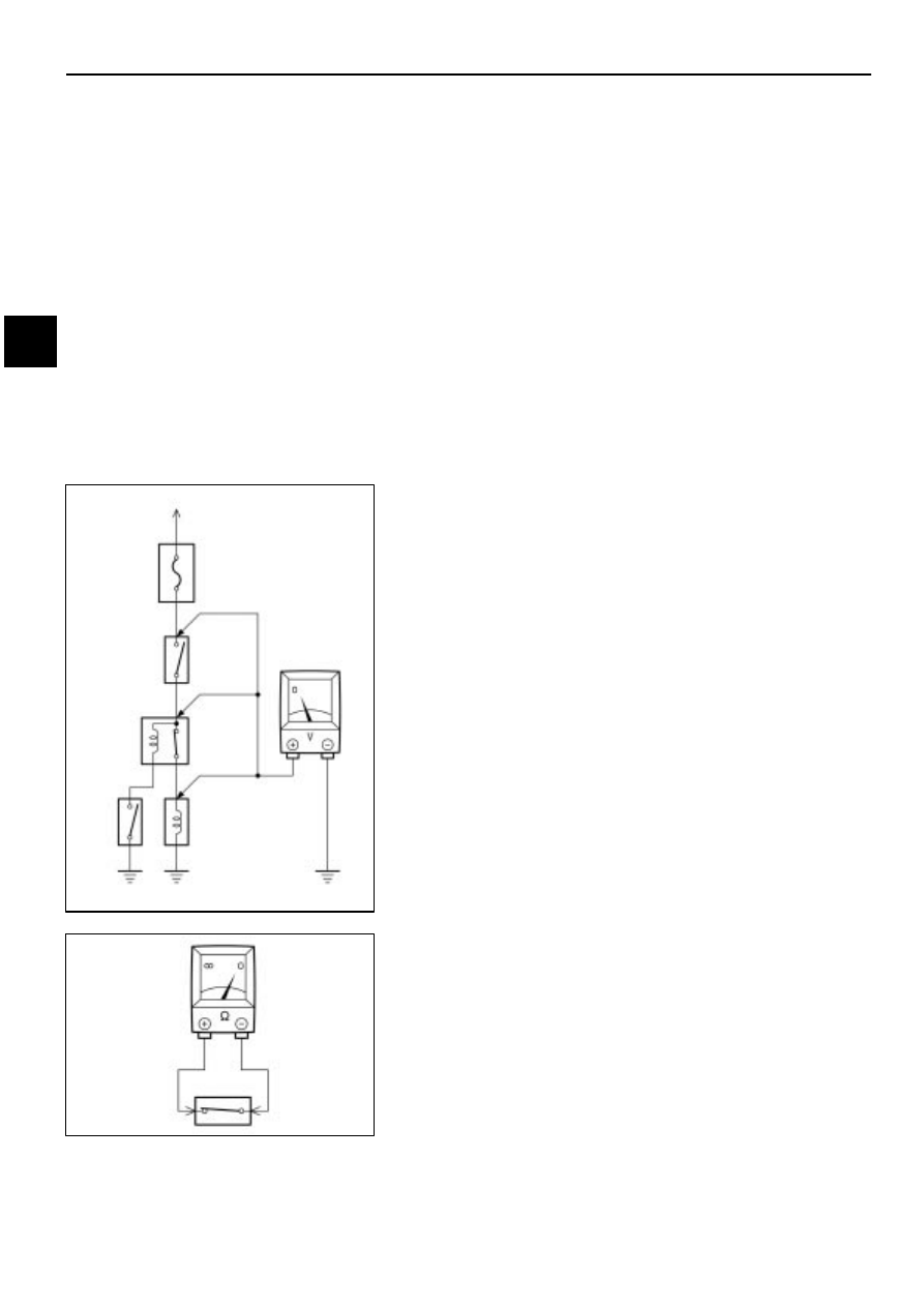
1.
Voltage Check
(a)
Establish conditions in which voltage is present at the
check point.
Example:
[A] – Ignition SW on
[B] – Ignition SW and SW 1 on
[C] – Ignition SW, SW 1 and Relay on (SW 2 off)
(b)
Using a voltmeter, connect the negative (–) lead to a
good ground point or negative (–) battery terminal
and the positive (+) lead to the connector or
component terminal. This check can be done with a
test bulb instead of a voltmeter.
2.
Continuity and Resistance Check
(a)
Disconnect the battery terminal or wire so there is no
voltage between the check points.
(b)
Contact the two leads of an ohmmeter to each of the
check points.
A
Diode
Ohmmeter
Diode
Ohmmeter
Digital Type
Analog Type
Bulb
Ohmmeter
A–6
INTRODUCTION–HOW TO PERFORM FOR SYSTEM INSPECTION
7
Wire Harness Repair Manual (RM1022E)
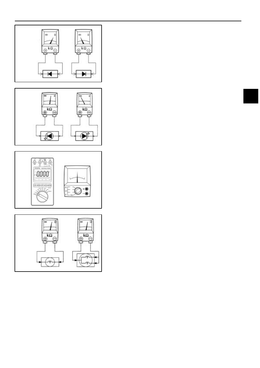
If the circuit has diodes, reverse the two leads and check
again.
When touching the negative (–) lead to the diode positive
(+) side and the positive (+) lead to the negative (–) side,
there should be continuity. When touching the two leads in
reverse, there should be no continuity.
HINT:
Specifications may vary depending on the type of
tester, so refer to the tester’s instruction manual before
performing the inspection.
Check LED (Light Emitting Diode) in the same manner as
that for diodes.
HINT:
Use a tester with a power source of 3V or greater to
overcome the circuit resistance.
If a suitable tester is not available, apply battery
voltage and check that the LED lights up.
(c)
Use a volt/ohmmeter with high impedance (10k
Ω
/V
minimum) for troubleshooting of the electrical circuit.
3.
Bulb Check
(a)
Remove the bulb.
(b)
There should be continuity between the respective
terminals of the bulb together with a certain amount
of resistance.
(c)
Apply the two leads of the ohmmeter to each of the
terminals.
(d)
Apply battery voltage and check that the bulb light up.
A
Fuse Case
Test Bulb
Short [A]
SW1
Short [B]
Relay
Light
Short [C]
SW2
Solenoid
Disconnect
Disconnect
Disconnect
To Ignition SW
IG Terminal
INTRODUCTION–HOW TO PERFORM FOR SYSTEM INSPECTION
A–7
8
Wire Harness Repair Manual (RM1022E)
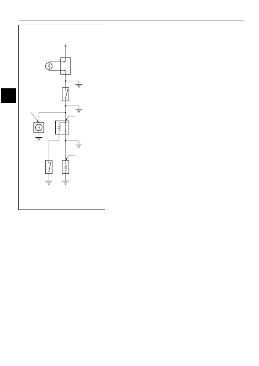
4.
Finding a Short Circuit
(a)
Remove the blown fuse and eliminate all loads from
the fuse.
(b)
Connect a test bulb in place of the fuse.
(c)
Establish conditions in which the test bulb comes on.
Example:
[A] – Ignition SW on
[B] – Ignition SW and SW 1 on
[C] – Ignition SW, SW 1 and Relay on (Connect the Relay)
and SW 2 off (or disconnect SW 2)
(d)
Disconnect and reconnect the connectors while
watching the test bulb. The short lies between the
connector where the test bulb stays lit and the
connector where the bulb goes out.
(e)
Find the exact location of the short by lightly shaking
the problem wire along the body.
CAUTION:
(a)
Do not open the cover or the case of the ECU
unless absolutely necessary. (If the IC terminals
are touched, the IC may be destroyed by static
electricity.)
(b)
When replacing the internal mechanism (ECU
part) of the digital meter, be careful that no part of
your body or clothing comes in contact with the
terminals of leads from the IC, etc. of the
replacement part (spare part).
A
D–200
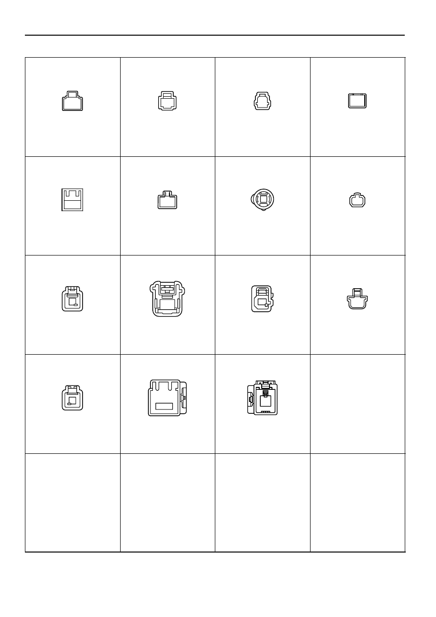
TABLE OF HOUSING SHAPE
Wire Harness Repair Manual (RM1022E)
275
<MALE> 1P Non–waterproof Type
1
1
1
1
90980–10160
90980–10178
90980–10182
90980–10251
1
1
1
1
90980–10433
90980–10253
90980–10342
90980–10396
90980–10434
1
90980–10870
90980–11026
1
1
1
90980–11097
90980–10994
90980–11146
90980–11258
1
1
1
90980–11737
90980–11774
90980–12041
Нет комментариевНе стесняйтесь поделиться с нами вашим ценным мнением.
Текст