Lexus ES300 (2002 year). Service manual — part 318
F41239
2
1
W04200
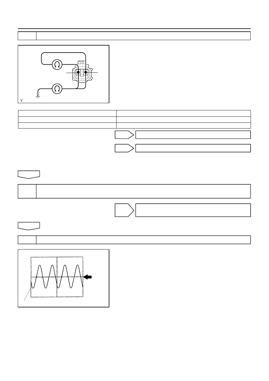
Normal Signal Waveform
1 V / Division
2 m/s / Division
GND
-
DIAGNOSTICS
ABS WITH EBD SYSTEM
05-253
406
2002 LEXUS ES300 REPAIR MANUAL (RM911U)
2
INSPECT FRONT SPEED SENSOR
(a)
Remove the front fender liner.
(b)
Make sure that there is no looseness at the connector
lock part and connecting part of the connector.
(c)
Disconnect the speed sensor connector.
(d)
Measure resistance between terminals 1 and 2 of speed
sensor connector.
OK: 1.4 - 1.8 k
Ω
at 20
C
(e)
Measure resistance between terminals 1 and 2 of speed
sensor connector and body ground.
OK: 1 M
Ω
or higher
A
OK
B
NG (Right front speed sensor)
C
NG (Left front speed sensor)
B
REPLACE SPEED SENSOR FRONT RH
C
REPLACE SPEED SENSOR FRONT LH
NOTICE:
Check the speed sensor signal last (See page
A
3
CHECK HARNESS AND CONNECTOR(SPEED SENSOR - SKID CONTROL ECU
ASSY)(See page
NG
REPAIR OR REPLACE HARNESS AND
CONNECTOR
OK
4
CHECK SPEED SENSOR AND SENSOR ROTOR SERRATIONS
(REFERENCE) INSPECTION USING OSCILLOSCOPE
(a)
Connect the oscilloscope to the terminals FR+ - FR-, FL+
- FL- of the skid control ECU.
(b)
Drive the vehicle with about 20 km/h (12 mph), and check
the signal waveform.
HINT:
As the vehicle speed (rpm of the wheels) increases, a
cycle of the waveform becomes shorter and the fluctua-
tion in the output voltage becomes greater.
When noise is identified in the waveform on the oscillo-
scope, error signals are generated due to the speed sen-
sor rotor’s scratches, looseness or foreign matter depos-
ited on it.

BR3795
OK
NG
05-254
-
DIAGNOSTICS
ABS WITH EBD SYSTEM
407
2002 LEXUS ES300 REPAIR MANUAL (RM911U)
OK
CHECK AND REPLACE BRAKE ACTUATOR
ASSY
NG
5
CHECK FRONT SPEED SENSOR INSTALLATION
(a)
Check the speed sensor installation.
The installation bolt is tightened properly and there is
no clearance between the sensor and front steering
knuckle.
Torque: 8.0 N
⋅
m (82 kgf
⋅
cm, 71 in.
⋅
lbf)
A
OK
B
NG (Right front speed sensor)
C
NG (Left front speed sensor)
B
REPLACE SPEED SENSOR FRONT RH
C
REPLACE SPEED SENSOR FRONT LH
NOTICE:
Check the speed sensor signal last (See page
A
6
CHECK SPEED SENSOR ROTOR AND SENSOR TIP
NG
CLEAN OR REPLACE SPEED SENSOR AND
SENSOR ROTOR SERRATIONS
NOTICE:
Check the speed sensor signal last (See page
OK
CHECK AND REPLACE BRAKE ACTUATOR ASSY
F41944
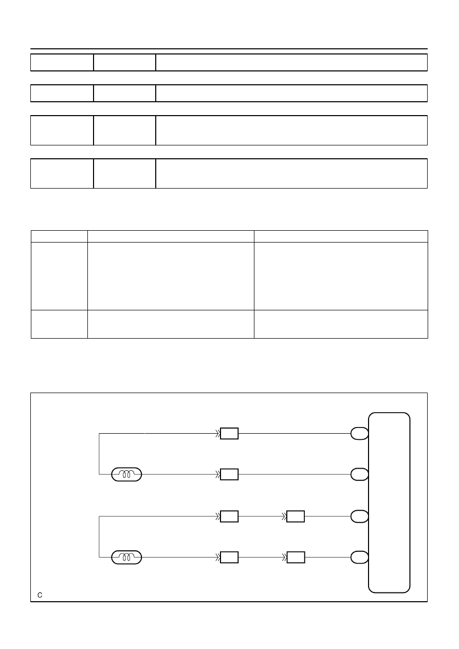
A36
ABS Speed Sensor
Rear LH
ID1
R
G
34
33
S1
12
15
11
A37
ABS Speed Sensor
Rear RH
G
R
L
P
13
14
3
1
2
1
2
RL-
RL+
RR-
RR+
S1
S1
S1
L
P
IF4
IF4
9
8
ID1
IO5
L
P
Skid Control ECU with Actuator
IO5
-
DIAGNOSTICS
ABS WITH EBD SYSTEM
05-255
408
2002 LEXUS ES300 REPAIR MANUAL (RM911U)
DTC
C0210/33 RIGHT REAR SPEED SENSOR CIRCUIT
DTC
C0215/34 LEFT REAR SPEED SENSOR CIRCUIT
DTC
C1238/38 FOREIGN MATTER IS ATTACHED ON TIP OF
RIGHT REAR SENSOR
DTC
C1239/39 FOREIGN MATTER IS ATTACHED ON TIP OF
LEFT REAR SENSOR
CIRCUIT DESCRIPTION
Refer to DTC C0200/31, C0205/32, C1235/35, C1236/36 on page
DTC No.
DTC Detecting Condition
Trouble Area
C0210/33
C0215/34
Detection of any of conditions from 1. to 4.:
1. With vehicle speed at 10 km/h or more, sensor signal
circuit of faulty wheel is open or short for 15 sec. or
longer.
2. Momentary interruption of sensor signal of faulty wheel
has occurred 7 times or more.
3. Sensor signal circuit is open for 0.5 sec. or longer.
Right rear, left rear speed sensor
Each speed sensor circuit
Sensor installation
Sensor rotor
C1238 / 38
C1239 / 39
Continuous noise occurs in to the speed sensor
signals with the vehicle speed at 20 km/h (12 mph)
or more continues for 5 sec or more.
Right rear, left rear speed sensor
Speed sensor rotor
HINT:
DTC No. C0210/33, C1238/38 is for the right rear speed sensor.
DTC No. C0215/34, C1239/39 is for the left rear speed sensor.
WIRING DIAGRAM
055XN-02
F10761
F10180
1
2
Connector 1
Connector 2
2
1
05-256
-
DIAGNOSTICS
ABS WITH EBD SYSTEM
409
2002 LEXUS ES300 REPAIR MANUAL (RM911U)
INSPECTION PROCEDURE
HINT:
Start the inspection from step 1 in case of using the hand-held tester and start from step 2 in case of not
using hand-held tester.
1
READ VALUE OF HAND-HELD TESTER(SKID CONTROL SENSOR)
(a)
Select the item ”WHEEL SPEED RL (RR)” in the DATA LIST and read its value displayed on the hand-
held tester.
(b)
Check that there is no difference between the speed value output from the speed sensor displayed
on the hand-held tester and the speed value displayed on the speedometer when driving the vehicle.
OK: There is almost no difference from the displayed speed value.
HINT:
There is tolerance of
±
10 % in the speedometer indication.
OK
CHECK AND REPLACE BRAKE ACTUATOR
ASSY
NG
2
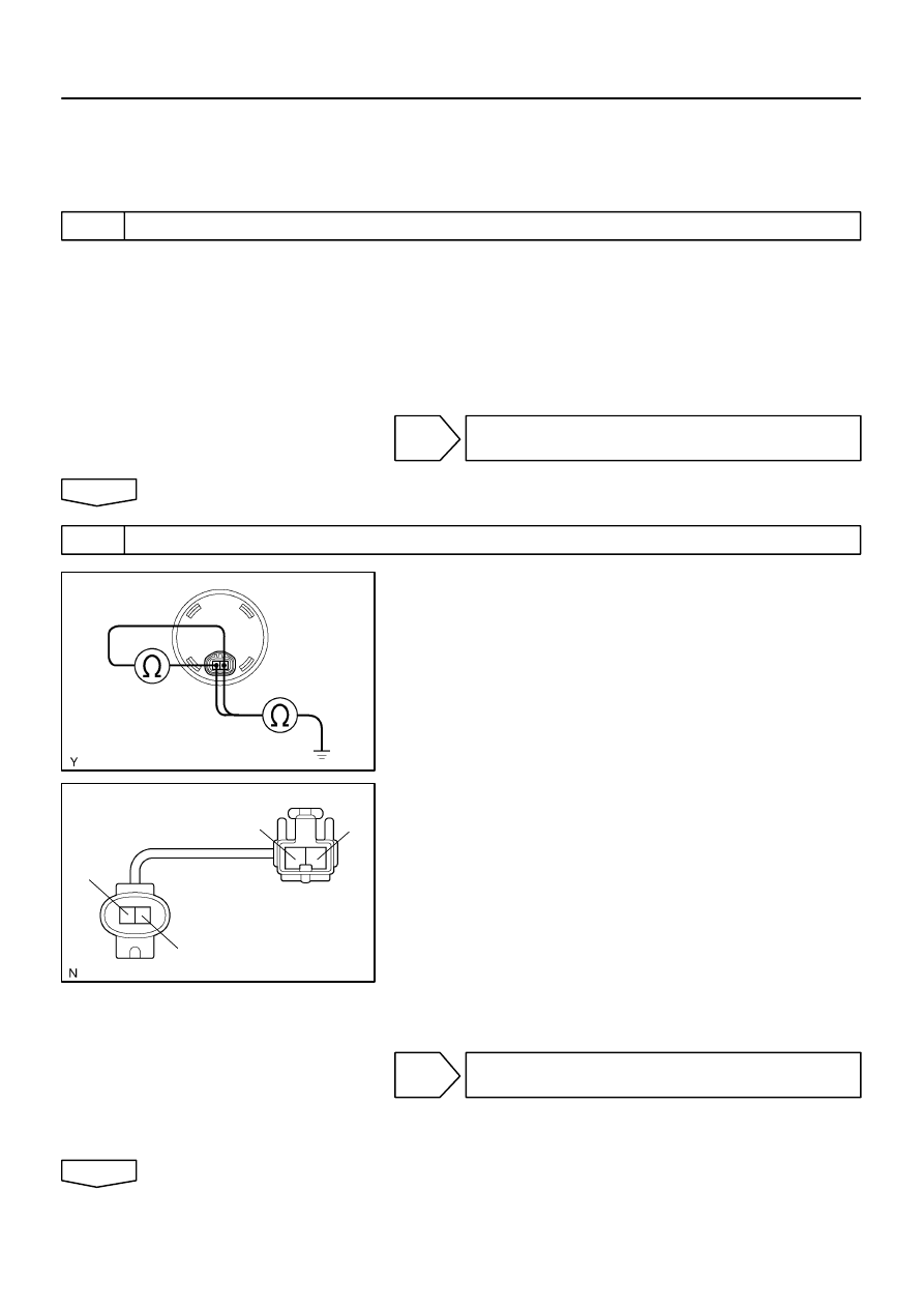
INSPECT SKID CONTROL SENSOR
(a)
Make sure that there is no looseness at the connector
lock part and connecting part of the connector.
(b)
Disconnect the sensor connector.
(c)
Measure resistance between terminals 1 and 2 of sensor
connector.
OK: 1.3 - 1.6 k
Ω
at 20
C
(d)
Measure resistance between terminals 1 and 2 of sensor
connector and body ground.
OK: 1 M
Ω
or higher
Skid control Sensor Sub-Wire Harness:
(a)
Remove the seat cushion and seatback.
(b)
Make sure that there is no looseness at the connector
lock part and connecting part of the connector.
(c)
Measure resistance between terminal 1 of connector 1
and terminal 2 of connector 2.
(d)
Measure resistance between terminal 2 of connector 1
and terminal 1 of connector 2.
OK: 1
Ω
or lower
(e)
Measure resistance between terminals 1 and 2 of speed
sensor connector 1 and body ground.
OK: 10 M
Ω
or higher
NG
REPLACE SKID CONTROL SENSOR OR
SUB-WIRE HARNESS
NOTICE:
Check the speed sensor signal last (See page
OK
Нет комментариевНе стесняйтесь поделиться с нами вашим ценным мнением.
Текст