Lexus SC300 / Lexus SC400. Service manual — part 452

(i)
Tighten the four mounting nuts.
Torque: 18 N
⋅
m (185 kgf
⋅
cm, 13 ft
⋅
lbf)
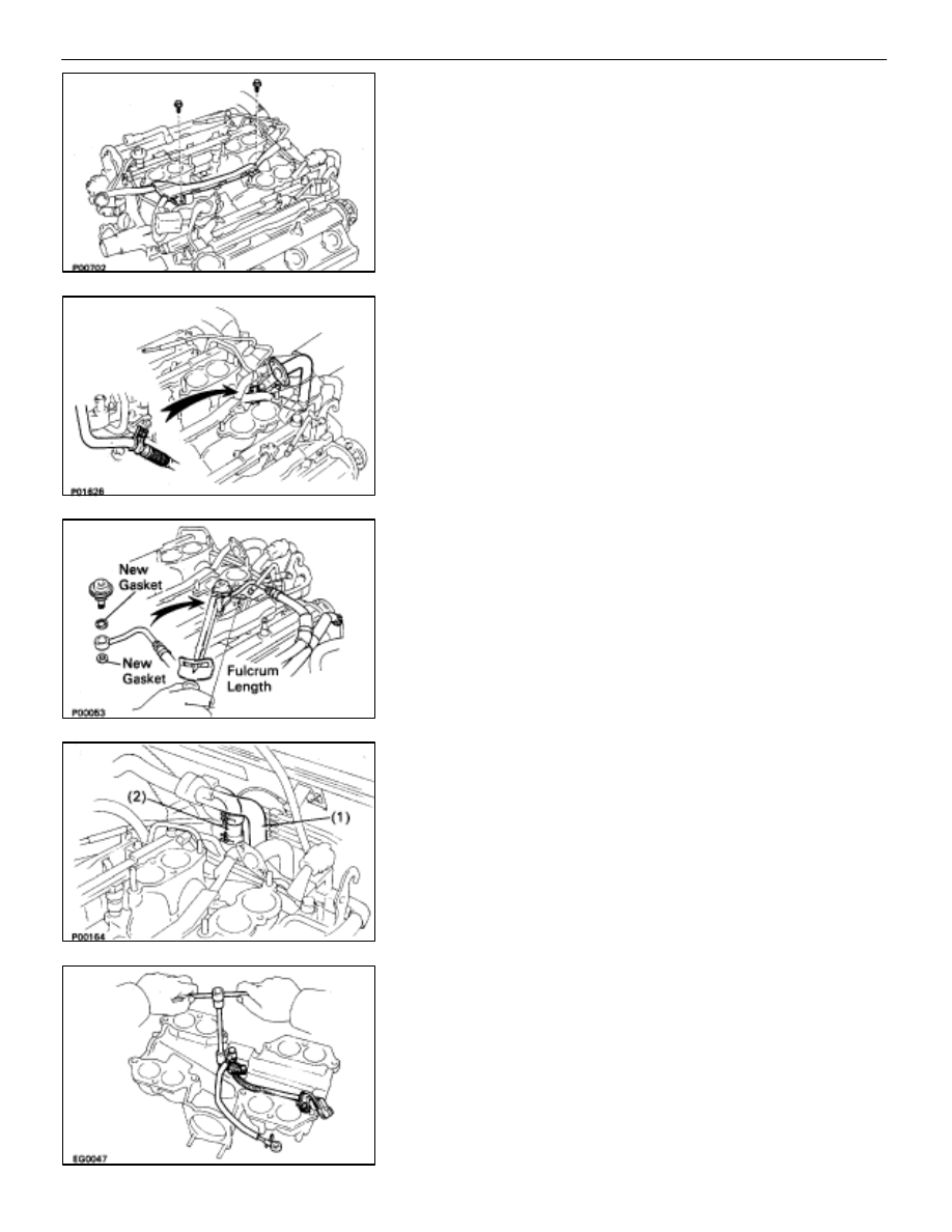
23. INSTALL FUEL RETURN PIPE
(a) Temporarily install the return pipe with the bolt, two new
gaskets and union bolt.
(b) Tighten the union bolt holding the return pipe to the fuel
pressure regulator.
Torque: 35 N
⋅
m (360 kgf
⋅
cm, 26 ft
⋅
lbf)
(c) Tighten
the bolt holding the return pipe to the LH cylinder
head.
24. INSTALL ENGINE WIRE TO DELIVERY PIPES, REAR
WATER BY–PASS JOINT AND RH CYLINDER HEAD
(a) Connect the eight injector connectors.
(b) Install the two engine wire connectors to connectors
bracket on the LH delivery pipe.
(c) Install the engine wire to the RH cylinder head with the
two bolts.
(d) Install the engine wire to the rear water by–pass joint
with the two bolts.
(e) Install the engine wire to the delivery pipes with the four
bolts.
EM–106
–
ENGINE MECHANICAL
Cylinder Heads
25. INSTALL ENGINE WIRE TO INTAKE MANIFOLD
Install the engine wire with the two bolts.
26. TEMPORARILY INSTALL EGR PIPE TO RH CYLINDER
HEAD
Temporarily install a new gasket and the EGR pipe with the
two bolts.
HINT: Use bolt 25 mm (0.98 in.) in length.
27. CONNECT
FUEL RETURN HOSE TO FUEL RETURN PIPE
28. CONNECT FUEL INLET HOSE TO LH DELIVERY PIPE
Connect the inlet hose with two new gaskets and the pulsa-
tion damper.
SST 09612–24012 (09617–24011)
Torque: 39 N
⋅
m (400 kgf
⋅
cm, 29 ft
⋅
lbf)
33 N
⋅
m (340 kgf
⋅
cm, 24 ft
⋅
lbf) for SST
HINT: Use a torque wrench with a fulcrum length of 30 cm
(11.81 in.).
29. CONNECT
HEATER
WATER
HOSES
Connect the following hoses:
(1)
Water hose to water by–pass pipe
(2)
Water hose to rear water by–pass joint
30. INSTALL AIR INTAKE CHAMBER
(a) Install the cold start injector, tube and wire assembly
with the three bolts.
Torque: 7.8 N
⋅
m (80 kgf
⋅
cm, 69 in.
⋅
lbf)
–
ENGINE MECHANICAL
Cylinder Heads
EM–107
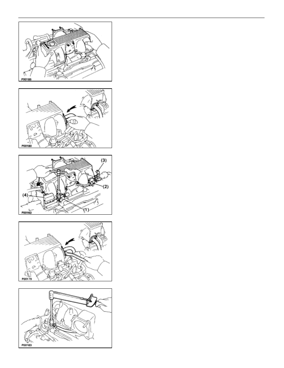
(b) Place four new gaskets on the intake manifold.
HINT: Gaskets can only be used twice before being replaced.
(c) Place the air intake chamber on the intake manifold.
(d) Temporarily connect the EGR pipe to the air intake
chamber with a new gasket and the two bolts.
HINT: Use bolts 20 mm (0.79 in.) in length.
(e) Temporarily install the air intake chamber and following
parts with the four bolts and eight nuts:
(1)
VSV for fuel pressure control system
(2)
(Exc. USA Spec.)
VSV for EGR system
(3)
A/T throttle cable bracket
(4)
Check connector (”DIAGNOSIS”) connector
(f) Uniformly tighten the bolts and nuts in several passes.
Torque: 18 N
⋅
m (185 kgf
⋅
cm, 13 ft
⋅
lbf)
HINT: Use bolts 40 mm (1.57 in.) in length.
(g) Tighten the two bolts holding the EGR pipe to the air
intake chamber.
Torque: 18 N
⋅
m (185 kgf
⋅
cm, 13 ft
⋅
lbf)
(h) Tighten the two bolts holding the EGR pipe to the RH
cylinder head.
Torque: 18 N
⋅
m (185 kgf
⋅
cm, 13 ft
⋅
lbf)
(i)
Connect the cold start injector tube to the RH delivery
pipe with the two new gaskets and the union bolt.
Torque: 15 N
⋅
m (150 kgf
⋅
cm, 11 ft
⋅
lbf)
(j)
Connect the following connectors:
•
Cold start injector connector
•
SV connector for fuel pressure control system
•
(Exc. USA Spec.)
VSV connector for EGR system
EM–108
–
ENGINE MECHANICAL
Cylinder Heads

31. INSTALL
ACCELERATOR
BRACKET
Install the bracket with the bolt and stud bolt.
32. INSTALL BRAKE BOOSTER UNION
Install the union with two new gaskets and the union bolt.
Torque: 29 N
⋅
m (300 kgf
⋅
cm, 22 ft
⋅
lbf)
33. CONNECT
VACUUM
HOSES
Connect the following hoses:
(1)
Vacuum hose to brake booster union
(2)
Vacuum hose (from VSV for heater water valve) to
air intake chamber
34. INSTALL THROTTLE BODY
(a) Connect the following hoses:
(1)
Water by–pass hose to throttle body
(2)
PCV hose to throttle body
(b) Install a new gasket and throttle body with the two bolts
and two nuts.
Torque: 18 N
⋅
m (185 kgf
⋅
cm, 13 ft
⋅
lbf)
HINT: Use bolts 40 mm (1.57 in.) in length.
(c) Install the water by–pass pipe (from rear water bypass
joint) to the clamp on the engine wire cover.
(d) Connect the following connectors:
(1) Throttle position sensor connector
(2) (w/ TRAC)
Sub–throttle position sensor connector
(3) (w/ TRAC)
Sub–throttle actuator connector
–
ENGINE MECHANICAL
Cylinder Heads
EM–109
Нет комментариевНе стесняйтесь поделиться с нами вашим ценным мнением.
Текст