Lexus SC300 / Lexus SC400. Service manual — part 218
TROUBLESHOOTING
Turn Signal and Hazard Warning Light
System
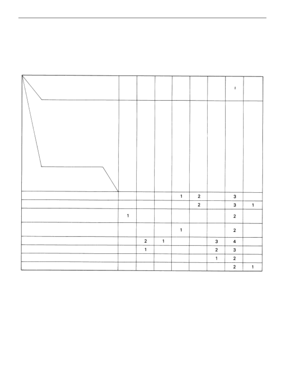
You will find the cause of trouble more easily using the table shown below. In this table, the numbers indicate
the order priority of the causes in trouble. Check each part in the order shown. If necessary, replace the parts.
See page
Part
name
Trouble
“Hazard” and “Turn” do not light up.
The flashing frequency is abnormal.
Hazard warning light does not light up.
(Turn is normal.)
Hazard warning light does not light up
in one direction.
*
Turn signal does not light up.
*
Turn signal does not light up.
Turn signal does not light up in one direction.
Only one bulb does not light up.
*
: Combination Meter, Wiper and Washer do not operate.
*
: Combination Meter, Wiper and Washer are normal.
HAZ–HORN Fuse
TURN Fuse
Ignition Switch
Hazard W
arning
Switch
T
urn Signal Flasher
T
urn Signal Switch
Wire Harness
Bulb
BE–4
, 21
BE–4
, 20
BE–26
BE–68
BE–68
BE–46
BE–6
BE–70
–
BODY ELECTRICAL SYSTEM
Lighting System

(ILLUMINATION LIGHT SYSTEM)
DESCRIPTION – ILLUMINATION LIGHT
SYSTEM
The component parts of this system and their function are described in the following table.
Parts Name
Function
Rheostat Light
In order to adjust the degree of illumination light, the resistance value of the built–in variable
g
Control Volume
j
g
g ,
resistor is sent to the combination meter and rheostat light control.
Integration Relay
During daytime running light operation this prevents current flow to the rheostat light control
g
y
(Daytime Running
g
y
g g
g
to stop each illumination from lighting up. When the light control switch is at TAIL or HEAD,
(
y
g
Light Relay: Canada)
g
g
g
current is sent to the rheostat light control.
PARTS LOCATION
–
BODY ELECTRICAL SYSTEM
Lighting System
BE–71
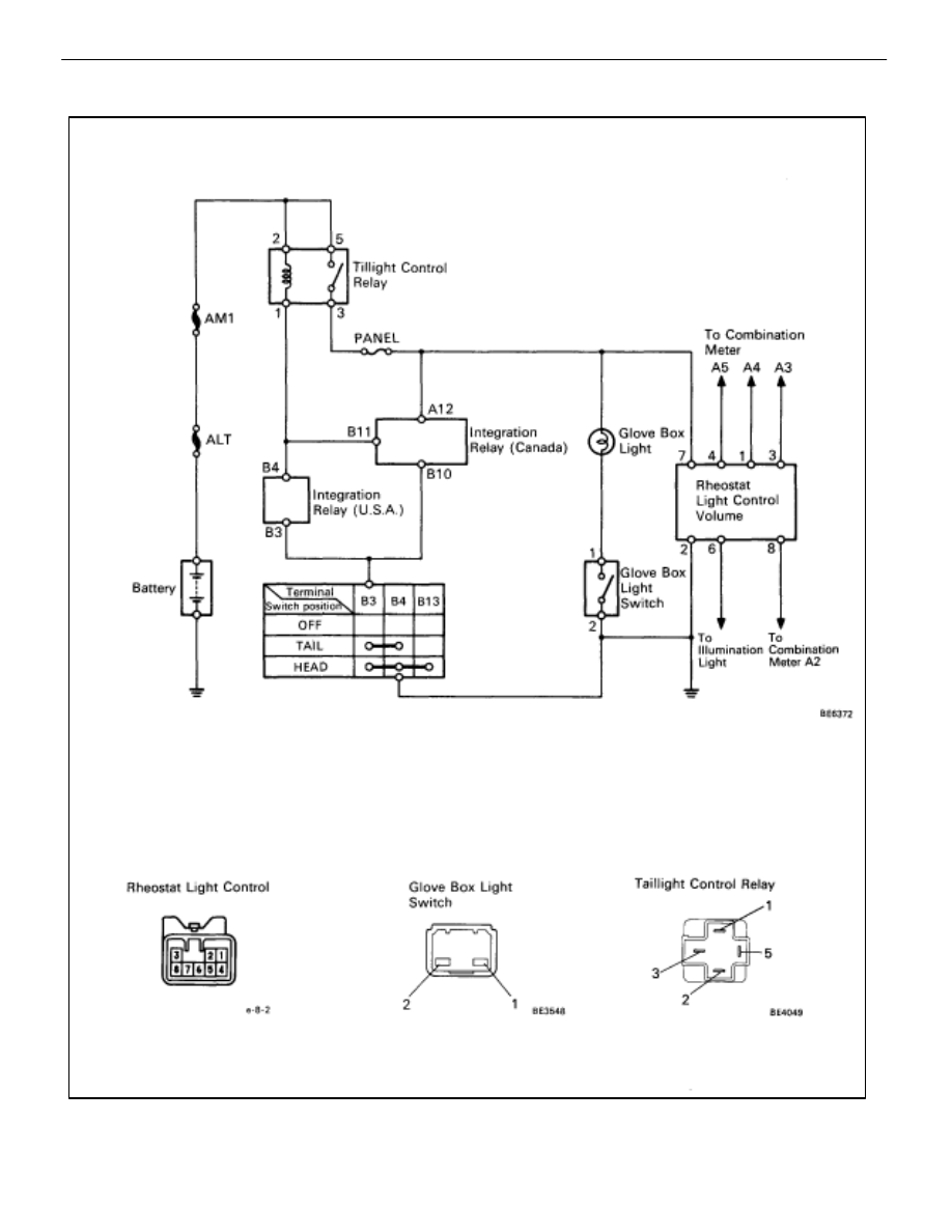
WIRING AND CONNECTOR DIAGRAMS
BE–72
–
BODY ELECTRICAL SYSTEM
Lighting System
Parts Inspection –
ILLUMINATION
LIGHT SYSTEM
(Rheostat Light Control Volume)
REMOVAL AND INSTALLATION OF
RHEOSTAT LIGHT CONTROL VOLUME
(See page
INSPECTION OF RHEOSTAT LIGHT
CONTROL VOLUME
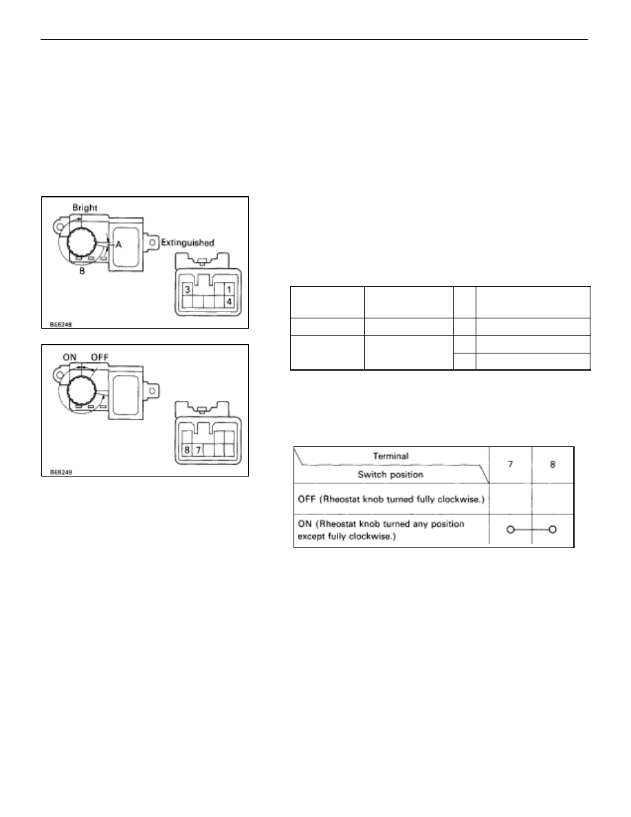
1. INSPECT RHEOSTAT LIGHT CONTROL VOLUME
(Resistance)
Inspection resistance between terminals.
Tester
Connection
Condition
Specified value
3–4
Constant
Approx. 10 k
1–3
Rheostat knob
A
1–3
turned clockwise
B
Approx. 10 k
→
0
If resistance is not as specified, replace the rheostat light con-
trol volume.
(Taillight Switch/Continuity)
Inspect continuity between terminals.
If operation is not as specified, replace the rheostat light con-
trol volume.
–
BODY ELECTRICAL SYSTEM
Lighting System
BE–73
Нет комментариевНе стесняйтесь поделиться с нами вашим ценным мнением.
Текст