Lexus SC300 / Lexus SC400. Service manual — part 733
–MEMO–
–
STEERING
STEERING COLUMN
SR–69

WIRING DIAGRAM
Sensor Power Source Circuit
CIRCUIT DESCRIPTION
Power to the position sensors, manual switch and auto set switch is output from the ECU.
DIAGNOSTIC CHART
DIAGNOSTIC CHART
SR–70
–
STEERING
STEERING COLUMN

OK
NG
OK
NG
OK
NG
INSPECTION PROCEDURE
1
Check voltage between terminals V
C
and E
1
of ECU connector.
C
OK
P
Remove ECU with connectors still connected.
Measure voltage between terminals V
C
and E
1
of ECU
connector.
Voltage:
4 – 6 V
Go to Step
.
2
Check for open in harness and connector between terminals Vc and E
1
of ECU connector.
Repair or replace harness or connector.
Proceed to next circuit inspection shown on ma-
trix chart (See page
3
Check for short in harness between terminal V
C
and E
1
of ECU connector.
Repair or replace harness or connector.
Check and replace ECU.
–
STEERING
STEERING COLUMN
SR–71
).
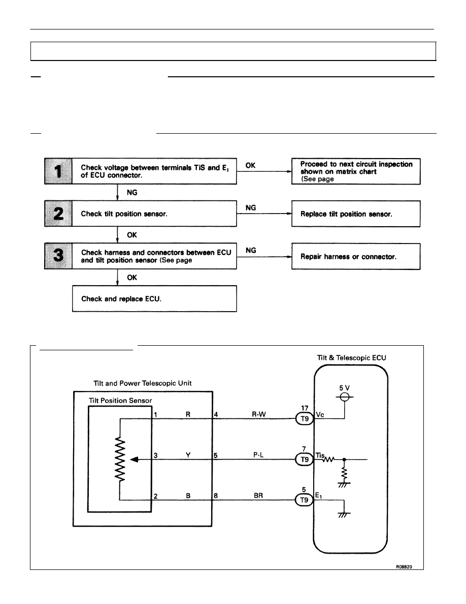
WIRING DIAGRAM
Tilt Position Sensor Circuit
CIRCUIT DESCRIPTION
The tilt position is sent to the ECU as a voltage signal from the position sensor.
A constant 5 V is supplied to terminal 1 of sensor.
The voltage at terminal 3 varies with position and is input to the ECU.
DIAGNOSTIC CHART
DIAGNOSTIC CHART
SR–72
–
STEERING
STEERING COLUMN
Нет комментариевНе стесняйтесь поделиться с нами вашим ценным мнением.
Текст