Lexus SC300 / Lexus SC400. Service manual — part 616

INSTALLATION OF ISC VALVE
(See Components on page
)
1.
INSTALL ISC VALVE
(a) Install
a
new gasket and the ISC valve with the two nuts.
Torque: 18 N
⋅
m (185 kgf
⋅
cm, 13 ft
⋅
lbf)
(b) Connect the following hoses to the ISC valve:
(1) Water by–pass hose (from throttle valve)
(2) Water by–pass hose (from water inlet housing)
(3) Water by–pass hose (from EGR valve)
(c) (USA
Spec.)
Install the vacuum pipe and water by–pass pipe (be-
tween ISC valve and EGR valve) to the air intake cham-
ber with the bolt.
(d) (Exc. USA Spec.)
Install the water by–pass pipe (between ISC valve and
EGR valve) to the VSV (for fuel pressure control) with
the bolt.
(e) Connect the ISC valve connector.
1.
INSTALL LOWER HIGH–TENSION CORD COVER
(See steps 5 to 13 and 16 to 18 on pages
to 41)
FI–83
EFI SYSTEM – Air Induction System (Idle Speed Control (ISC) Valve)
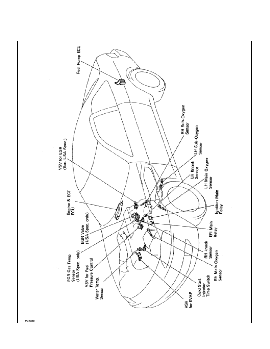
ELECTRONIC CONTROL SYSTEM
Location of Electronic Control Parts
FI–84
– Electronic Control System (Location of Electronic Control Parts)
EFI SYSTEM

EFI Main Relay
INSPECTION OF EFI MAIN RELAY
1. REMOVE
EFI MAIN RELAY FROM RELAY BOX IN ENGINE
COMPARTMENT
2.
INSPECT EFI MAIN RELAY
A. Inspect relay continuity
(a) Using an ohmmeter, check that there is continuity
between terminals 1 and 3.
(b) Check that there is no continuity between terminals 2
and 4.
If continuity is not as specified, replace the relay.
B. Inspect relay operation
(a) Apply battery voltage across terminals 1 and 3.
(b) Using an ohmmeter, check that there is continuity
between terminals 2 and 4.
If operation is not as specified, replace the relay.
3.
REINSTALL EFI MAIN RELAY
FI–85
– Electronic Control System (EFI Main Relay)
EFI SYSTEM

Ignition Main Relay
INSPECTION OF IGNITION MAIN RELAY
1.
REMOVE IGNITION MAIN RELAY FROM RELAY BOX IN
ENGINE COMPARTMENT
2.
INSPECT IGNITION MAIN RELAY
A. Inspect relay continuity
(a) Using an ohmmeter, check that there is continuity
between terminals 3 and 6.
(b) Check that there is continuity between terminals 4 and
5.
(c) Check that there is no continuity between terminals 1
and 2.
If continuity is not as specified, replace the relay.
B. Inspect relay operation
(a) Apply battery voltage across terminals 3 and 6.
(b) Using an ohmmeter, check that there is continuity
between terminals 1 and 2.
(c) Apply battery voltage across terminals 4 and 5.
(d) Check that there is continuity between terminals 1 and
2.
If operation is not as specified, replace the relay.
3.
REINSTALL IGNITION MAIN RELAY
FI–86
– Electronic Control System (Ignition Main Relay)
EFI SYSTEM
Нет комментариевНе стесняйтесь поделиться с нами вашим ценным мнением.
Текст