Lexus SC300 / Lexus SC400. Service manual — part 536
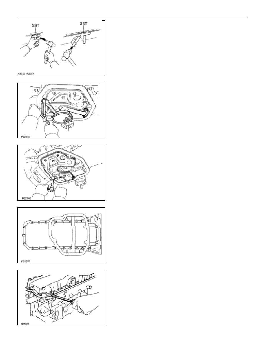
(b) Insert the blade of SST between the No.1 and No.2 oil
pan, break the seal of the applied sealer and remove the
No.1 oil pan.
SST 09032–00100
NOTICE:
•
Be careful not to damage the No.2 oil pan contact surface
of the No.1 oil pan.
•
Be careful not to damage the oil pan flange.
9.
REMOVE OIL STRAINER
Remove the bolt, two nuts, oil strainer and gasket.
10. REMOVE OIL PAN BAFFLE PLATE
Remove the five bolts, two nuts and baffle plate.
11. REMOVE NO.1 OIL PAN
(a) Remove the 22 mounting bolts.
(b) Remove
the No.1 oil pan by prying the portions between
the cylinder block and No.1 oil pan with a screwdriver.
NOTICE: Be careful not to damage the contact surfaces
of the cylinder block and No.1 oil pan.
(c) Remove the O–ring from the cylinder block.
–
LUBRICATION SYSTEM
Oil Pump
LU–11

12. REMOVE OIL PUMP
(a) Remove the nine mounting bolts.
(b) Using a hammer and a brass bar, remove the oil pump
by carefully tapping the oil pump body.
(c) Remove the two O–ring from the cylinder block.
COMPONENTS FOR DISASSEMBLY AND
ASSEMBLY OF OIL PUMP
LU–12
–
LUBRICATION SYSTEM
Oil Pump

DISASSEMBLY OF OIL PUMP
(See Components on page
1.
REMOVE RELIEF VALVE
(a) Slighty mount the pump body in a vise.
(b) Remove the plug, gasket, compression spring and relief
valve.
NOTICE: Be careful not to damage the pump body.
2.
REMOVE DRIVE AND DRIVEN ROTORS
Remove the ten screws, pump body cover, the drive and
driven rotors.
INSPECTION OF OIL PUMP
1.
INSPECT RELIEF VALVE
Coat the valve with engine oil and check that it falls smoothly
into the valve hole on its own weight.
If it doesn’t, replace the relief valve. If necessary, replace the
oil pump assembly.
2.
INSPECT DRIVE AND DRIVEN ROTORS
A. Place drive and driven rotors into oil pump body
The marks on the rotors must face up.
B.
Inspect rotor tip clearance
Using a feeler gauge, measure the clearance between the
drive and driven rotors.
Standard tip clearance:
0.310–0.490 mm
(0.0122–0.0193 in.)
Maximum tip clearance: 0.53 mm (0.0209 in.)
If the tip clearance is greater than maximum, replace the ro-
tors as a set.
–
LUBRICATION SYSTEM
Oil Pump
LU–13

C. Inspect rotor body clearance
Using a feeler gauge, measure the clearance between the
driven rotor and pump body.
Standard body clearance:
0.100–0.175 mm
(0.0039–0.0069 in.)
Maximum body clearance: 0.20 mm (0.0079 in.)
If the body clearance is greater than maximum, replace the
rotors as a set. If necessary, replace the oil pump assembly.
D. Inspect rotor side clearance
Using a feeler gauge and precision straight edge, measure
the clearance between the rotors and precision straight
edge.
Standard side clearance:
0.030–0.090 mm
(0.0012–0.0035 in.)
Maximum side clearance:
0.12 mm (0.0047 in.)
If the side clearance is greater than maximum, replace the ro-
tors as a set. If necessary, replace the oil pump assembly.
E. Remove drive and driven rotors
REPLACEMENT OF CRANKSHAFT
FRONT OIL SEAL
(See page
ASSEMBLY OF OIL PUMP
(See Components on page
1.
INSTALL DRIVE AND DRIVEN ROTORS
(a) Place
the drive and driven rotors into oil pump body with
the mark facing upward.
(b) Install the pump body cover with the ten screws.
Torque: 10 N
⋅
m (105 kgf
⋅
cm, 8 ft
⋅
lbf)
LU–14
–
LUBRICATION SYSTEM
Oil Pump
Нет комментариевНе стесняйтесь поделиться с нами вашим ценным мнением.
Текст