Lexus SC300 / Lexus SC400. Service manual — part 150
(Nakamichi)
1.
REMOVE POWER AMPLIFIER
(a) Remove the RH side cover.
(b) Remove the CD auto changer (See page
).
(c) Disconnect three connectors and remove three nuts and the
power amplifier with the bracket.
(d) Remove four bolts and the power amplifier.
2.
INSTALL WOOFER AMPLIFIER
For installation follow the removal procedure in reverse.
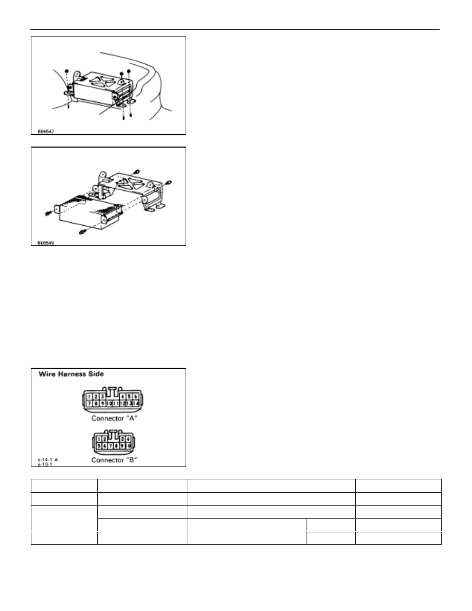
POWER AMPLIFIER INSPECTION
INSPECT POWER AMPLIFIER
(Circuit)
Disconnect the connector from power amplifier and inspect
the connector on the wire harness side as shown.
(Produced by PIONEER)
ÑÑÑÑÑÑÑ
ÑÑÑÑÑÑÑ
Check for
ÑÑÑÑÑÑÑÑ
ÑÑÑÑÑÑÑÑ
Tester connection
ÑÑÑÑÑÑÑÑÑÑÑÑÑÑÑ
ÑÑÑÑÑÑÑÑÑÑÑÑÑÑÑ
Condition
ÑÑÑÑÑÑÑÑ
ÑÑÑÑÑÑÑÑ
Specified value
ÑÑÑÑÑÑÑ
ÑÑÑÑÑÑÑ
Continuity
ÑÑÑÑÑÑÑÑ
ÑÑÑÑÑÑÑÑ
B7–Ground
ÑÑÑÑÑÑÑÑÑÑÑÑÑÑÑ
ÑÑÑÑÑÑÑÑÑÑÑÑÑÑÑ
Constant
ÑÑÑÑÑÑÑÑ
ÑÑÑÑÑÑÑÑ
Continuity
ÑÑÑÑÑÑÑ
ÑÑÑÑÑÑÑ
Voltage
ÑÑÑÑÑÑÑÑ
ÑÑÑÑÑÑÑÑ
B10–Ground
ÑÑÑÑÑÑÑÑÑÑÑÑÑÑÑ
ÑÑÑÑÑÑÑÑÑÑÑÑÑÑÑ
Constant
ÑÑÑÑÑÑÑÑ
ÑÑÑÑÑÑÑÑ
Battery positive voltage
ÑÑÑÑÑÑÑ
ÑÑÑÑÑÑÑ
ÑÑÑÑÑÑÑÑ
ÑÑÑÑÑÑÑÑ
A14–Ground
A6 G
d
ÑÑÑÑÑÑÑÑÑÑÑ
ÑÑÑÑÑÑÑÑÑÑÑ
Ignition switch position
ÑÑÑÑÑ
ÑÑÑÑÑ
ACC or ON
ÑÑÑÑÑÑÑÑ
ÑÑÑÑÑÑÑÑ
Battery positive voltage
ÑÑÑÑÑÑÑ
ÑÑÑÑÑÑÑ
ÑÑÑÑÑÑÑÑ
ÑÑÑÑÑÑÑÑ
A6–Ground
ÑÑÑÑÑÑÑÑÑÑÑ
ÑÑÑÑÑÑÑÑÑÑÑ
ÑÑÑÑÑ
ÑÑÑÑÑ
LOCK
ÑÑÑÑÑÑÑÑ
ÑÑÑÑÑÑÑÑ
No voltage
If circuit is not as specified, refer to
wiring diagrams
and inspect the circuits connected to other parts.
–
BODY ELECTRICAL SYSTEM
AUDIO SYSTEM
BE–211
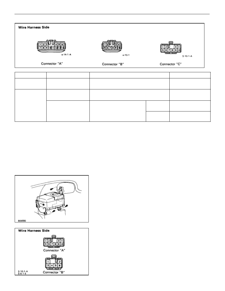
(Produced by NAKAMICHI)
ÑÑÑÑÑÑÑ
ÑÑÑÑÑÑÑ
Check for
ÑÑÑÑÑÑÑÑ
ÑÑÑÑÑÑÑÑ
Tester connection
ÑÑÑÑÑÑÑÑÑÑÑÑÑÑÑ
ÑÑÑÑÑÑÑÑÑÑÑÑÑÑÑ
Condition
ÑÑÑÑÑÑÑÑ
ÑÑÑÑÑÑÑÑ
Specified value
ÑÑÑÑÑÑÑ
ÑÑÑÑÑÑÑ
ÑÑÑÑÑÑÑ
Continuity
ÑÑÑÑÑÑÑÑ
ÑÑÑÑÑÑÑÑ
ÑÑÑÑÑÑÑÑ
B7–Ground
C7–Ground
ÑÑÑÑÑÑÑÑÑÑÑÑÑÑÑ
ÑÑÑÑÑÑÑÑÑÑÑÑÑÑÑ
ÑÑÑÑÑÑÑÑÑÑÑÑÑÑÑ
Constant
ÑÑÑÑÑÑÑÑ
ÑÑÑÑÑÑÑÑ
ÑÑÑÑÑÑÑÑ
Continuity
ÑÑÑÑÑÑÑ
ÑÑÑÑÑÑÑ
ÑÑÑÑÑÑÑ
Voltage
ÑÑÑÑÑÑÑÑ
ÑÑÑÑÑÑÑÑ
ÑÑÑÑÑÑÑÑ
B10–Ground
C3–Ground
ÑÑÑÑÑÑÑÑÑÑÑÑÑÑÑ
ÑÑÑÑÑÑÑÑÑÑÑÑÑÑÑ
ÑÑÑÑÑÑÑÑÑÑÑÑÑÑÑ
Constant
ÑÑÑÑÑÑÑÑ
ÑÑÑÑÑÑÑÑ
ÑÑÑÑÑÑÑÑ
Battery positive voltage
ÑÑÑÑÑÑÑ
ÑÑÑÑÑÑÑ
ÑÑÑÑÑÑÑ
ÑÑÑÑÑÑÑÑ
ÑÑÑÑÑÑÑÑ
ÑÑÑÑÑÑÑÑ
A6–Ground
A14–Ground
ÑÑÑÑÑÑÑÑÑÑÑ
ÑÑÑÑÑÑÑÑÑÑÑ
ÑÑÑÑÑÑÑÑÑÑÑ
Ignition switch position
ÑÑÑÑÑ
ÑÑÑÑÑ
ÑÑÑÑÑ
ACC or ON
ÑÑÑÑÑÑÑÑ
ÑÑÑÑÑÑÑÑ
ÑÑÑÑÑÑÑÑ
Battery positive voltage
ÑÑÑÑÑÑÑ
ÑÑÑÑÑÑÑ
ÑÑÑÑÑÑÑ
ÑÑÑÑÑÑÑÑ
ÑÑÑÑÑÑÑÑ
ÑÑÑÑÑÑÑÑ
C4–Ground
C6–Ground
ÑÑÑÑÑÑÑÑÑÑÑ
ÑÑÑÑÑÑÑÑÑÑÑ
ÑÑÑÑÑÑÑÑÑÑÑ
Ignition switch position
ÑÑÑÑÑ
ÑÑÑÑÑ
ÑÑÑÑÑ
LOCK
ÑÑÑÑÑÑÑÑ
ÑÑÑÑÑÑÑÑ
ÑÑÑÑÑÑÑÑ
No voltage
If circuit is not as specified, refer to
wiring diagrams
and inspect the circuits connected to other parts.
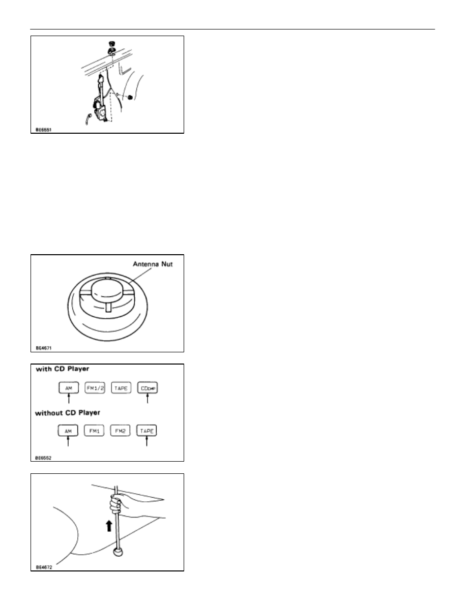
CD AUTO CHANGER
CD AUTO CHANGER REMOVAL AND
INSTALLATION
1.
REMOVE CD AUTO CHANGER
(a) Remove RH side cover.
(b) Disconnect two connectors.
(c) Remove three bolts, one nut and the CD auto changer.
CD AUTO CHANGER INSPECTION
INSPECT CD AUTO CHANGER
(Circuit)
Disconnect connectors from CD auto changer and inspect
the connector on the wire harness side as shown.
BE–212
–
BODY ELECTRICAL SYSTEM
AUDIO SYSTEM

ÑÑÑÑÑÑÑ
ÑÑÑÑÑÑÑ
Check for
ÑÑÑÑÑÑÑÑ
ÑÑÑÑÑÑÑÑ
Tester connection
ÑÑÑÑÑÑÑÑÑÑÑÑÑÑÑ
ÑÑÑÑÑÑÑÑÑÑÑÑÑÑÑ
Condition
ÑÑÑÑÑÑÑÑ
ÑÑÑÑÑÑÑÑ
Specified value
ÑÑÑÑÑÑÑ
ÑÑÑÑÑÑÑ
Voltage
ÑÑÑÑÑÑÑÑ
ÑÑÑÑÑÑÑÑ
A4–Ground
ÑÑÑÑÑÑÑÑÑÑÑÑÑÑÑ
ÑÑÑÑÑÑÑÑÑÑÑÑÑÑÑ
Constant
ÑÑÑÑÑÑÑÑ
ÑÑÑÑÑÑÑÑ
Battery positive voltage
ÑÑÑÑÑÑÑ
ÑÑÑÑÑÑÑ
ÑÑÑÑÑÑÑÑ
ÑÑÑÑÑÑÑÑ
A3–Ground
ÑÑÑÑÑÑÑÑÑÑÑ
ÑÑÑÑÑÑÑÑÑÑÑ
Ignition switch
iti
ÑÑÑÑÑ
ÑÑÑÑÑ
ACC or ON
ÑÑÑÑÑÑÑÑ
ÑÑÑÑÑÑÑÑ
Battery positive voltage
ÑÑÑÑÑÑÑ
ÑÑÑÑÑÑÑ
ÑÑÑÑÑÑÑÑ
ÑÑÑÑÑÑÑÑ
A3–Ground
ÑÑÑÑÑÑÑÑÑÑÑ
ÑÑÑÑÑÑÑÑÑÑÑ
position
ÑÑÑÑÑ
ÑÑÑÑÑ
LOCK
ÑÑÑÑÑÑÑÑ
ÑÑÑÑÑÑÑÑ
No voltage
ÑÑÑÑÑÑÑ
ÑÑÑÑÑÑÑ
Continuity
ÑÑÑÑÑÑÑÑ
ÑÑÑÑÑÑÑÑ
A7–Ground
ÑÑÑÑÑÑÑÑÑÑÑ
ÑÑÑÑÑÑÑÑÑÑÑ
Luggage compartment
d
t
it h
ÑÑÑÑÑ
ÑÑÑÑÑ
Push (OFF)
ÑÑÑÑÑÑÑÑ
ÑÑÑÑÑÑÑÑ
No continuity
ÑÑÑÑÑÑÑ
ÑÑÑÑÑÑÑ
ÑÑÑÑÑÑÑÑ
ÑÑÑÑÑÑÑÑ
A7–Ground
ÑÑÑÑÑÑÑÑÑÑÑ
ÑÑÑÑÑÑÑÑÑÑÑ
door courtesy switch
ÑÑÑÑÑ
ÑÑÑÑÑ
Free (ON)
ÑÑÑÑÑÑÑÑ
ÑÑÑÑÑÑÑÑ
Continuity
If circuit is not as specified, refer to
, 203 wiring dia-
grams and inspect the circuits connected to other parts.
HINT:
•
Check the wire harness between the radio receiver
assembly and the CD auto changer in accordance with
the wiring diagrams in
•
Since the signals to and from the CDL+, CDL, CDR+,
CDR, TXM+, TXM, TXS+ and TXS terminals are serial
signals, they cannot ordinarily be measured with a
tester.
LUGGAGE COMPARTMENT DOOR
COURTESY SWITCH
(See page
–
BODY ELECTRICAL SYSTEM
AUDIO SYSTEM
BE–213
MOTOR ANTENNA
MOTOR ANTENNA REMOVAL AND
INSTALLATION
1. REMOVE
MOTOR
ANTENNA
(a) Remove the antenna nut.
(b) Remove the LH side cover.
(c) Disconnect the motor antenna connector and the antenna
cord.
(d) Remove the nut and the motor antenna assembly.
2. INSTALL
MOTOR
ANTENNA
(a) Install the antenna nut.
(b) Connect the motor antenna connector and the antenna cord.
(c) Install the nut.
ANTENNA ROD REMOVAL AND
INSTALLATION
1.
REMOVE ANTENNA ROD
HINT: Perform this operation with the battery negative (–)
cable connected to the battery terminal.
(a) Turn the ignition switch to ”LOCK” position.
(b) Remove the antenna nut.
(c–1) with CD player
Press the ”AM” and ”CD” buttons on the radio receiver, and
simultaneously turn the ignition switch to ”ACC” position.
(c–2) without CD player
Press the ”AM” and ”TAPE” buttons on the radio receiver, and
simultaneously turn the ignition switch to ”ACC” position.
HINT:
•
The rod will extend fully and be released from the motor
antenna.
•
After removing the antenna rod, leave the ignition switch
at ”ACC”.
NOTICE: To prevent body damage when the antenna rod is re-
leased, hold the rod while it comes out.
BE–214
–
BODY ELECTRICAL SYSTEM
AUDIO SYSTEM
Нет комментариевНе стесняйтесь поделиться с нами вашим ценным мнением.
Текст