Lexus SC300 / Lexus SC400. Service manual — part 572
G.
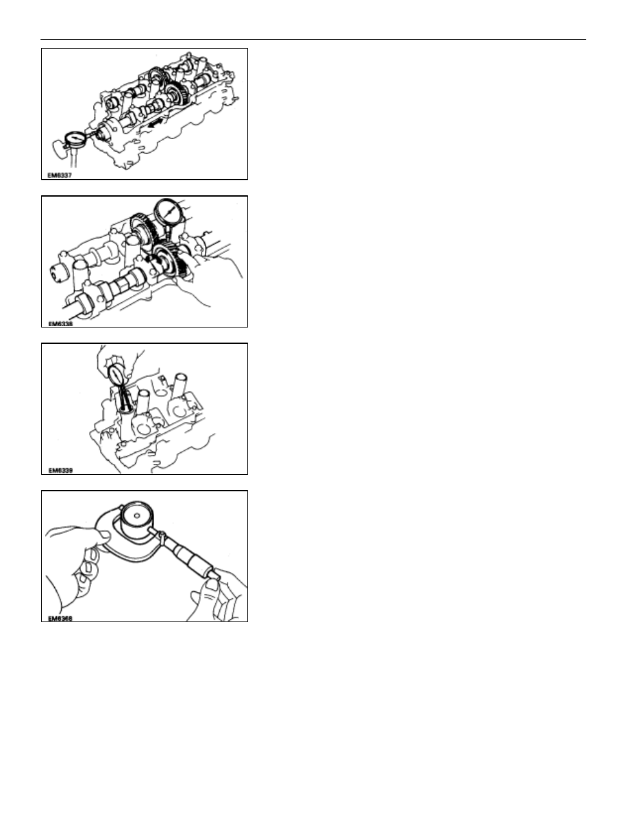
Inspect camshaft thrust clearance
(a) Install the camshafts.
(b) Using a dial indicator, measure the thrust clearance
while moving the camshaft back and forth.
Standard thrust clearance: 0.040–0.090 mm
(0.0016–0.0035 in.)
Maximum thrust clearance: 0.12 mm (0.0047 in.)
If the thrust clearance is greater than maximum, replace the
camshaft. If necessary, replace the bearing caps and cylin-
der head as a set.
H.
Inspect camshaft gear backlash
(a) Install
the
camshafts
without installing the exhaust
camshaft sub–gear.
(See step 7 on pages
(b) Using a dial indicator, measure the backlash.
Standard backlash: 0.020–0.200 mm
(0.0008–0.0079 in.)
Maximum backlash: 0.30 mm (0.0188 in.)
If the backlash is greater than maximum, replace the cam-
shafts.
11. INSPECT VALVE LIFTERS AND LIFTER BORES
(a) Using a caliper gauge, measure the lifter bore diameter
of the cylinder head.
Lifter bore diameter: 31.000–31.016 mm
(1.2205–1.2211 in.)
(b) Using a micrometer, measure the lifter diameter.
Lifter diameter: 30.966–30.976 mm
(1.2191–1.2195 in.)
(c) Subtract the lifter diameter measurement from the lifter
bore diameter measurement.
Standard oil clearance: 0.024–0.050 mm
(0.0009–0.0020 in.)
Maximum oil clearance: 0.07 mm (0.0028 in.)
If the oil clearance is greater than maximum, replace the lifter.
If necessary, replace the cylinder head.
–
ENGINE MECHANICAL
Cylinder Heads
EM–87
12. INSPECT AIR INTAKE CHAMBER
Using a precision straight edge and feeler gauge, measure
the surfaces contacting the intake manifold for warpage.
Maximum warpage: 0.15 mm (0.0059 in.)
If warpage is greater than maximum, replace the chamber.
13. INSPECT
INTAKE
MANIFOLD
Using a precision straight edge and feeler gauge, measure
the surfaces contacting the cylinder head and air intake
chamber for warpage.
Maximum warpage: 0.15 mm (0.0059 in.)
If warpage is greater than maximum, replace the manifold.
14. INSPECT EXHAUST MANIFOLD
Using a precision straight edge and feeler gauge, measure
the surfaces contacting the cylinder head for warpage.
Maximum warpage: 1.00 mm (0.0394 in.)
If warpage is greater than maximum, replace the manifold.
15. INSPECT CYLINDER HEAD BOLTS
Using a vernier caliper, measure the thread outside diameter
of the bolt.
Standard outside diameter: 9.770–9.960 mm
(0.3846–0.3921 in.)
Minimum outside diameter: 9.60 mm (0.3780 in.)
If the diameter is less than minimum, replace the bolt.
EM–88
–
ENGINE MECHANICAL
Cylinder Heads
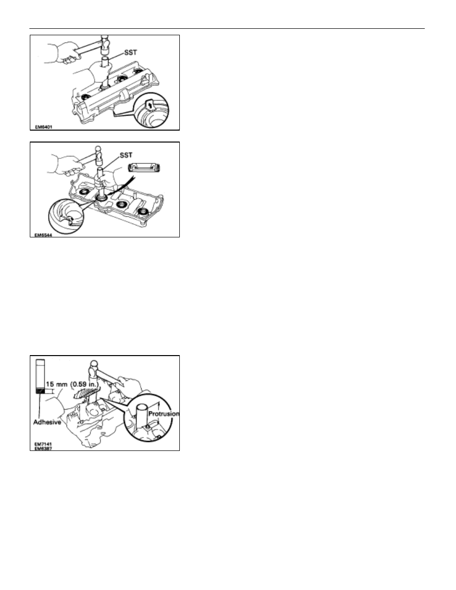
16. IF NECESSARY, REPLACE SPARK PLUG TUBE
GASKETS
(a) Bend the ventilation case claw installed on the cylinder
head cover to an angle of 905 or more.
(b) Using SST and a hammer, tap out the gasket.
SST 09550–10012 (09552–10010, 09560–10010)
(c) Using SST and a hammer, tap in a new gasket until its
surface is flush with the upper edge of the cylinder head
cover.
SST 09550–10012 (09552–10010, 09560–10010)
(d) Apply a light coat of MP grease to the gasket lip.
(e) Return the ventilation case claw to its original position.
ASSEMBLY OF CYLINDER HEADS
(See Components on page
HINT:
•
Thoroughly clean all parts to be assembled.
•
Before installing the parts, apply new engine oil to all
sliding and rotating surfaces.
•
Replace all gaskets and oil seals with new ones.
1.
INSTALL SPARK PLUG TUBES
HINT: When using a new cylinder head, spark plug tubes
must be installed.
(a) Apply adhesive to the end of the spark plug tube.
Adhesive: Part No.08833–00070, THREE BOND 1324
or equivalent
(b) Using a wooden block and hammer, tap in a new spark
plug tube until there is 48.7–49.3 mm (1.917 –1.941 in.)
protruding from the camshaft bearing cap installation
surface of the cylinder head.
NOTICE: Avoid tapping a new spark plug tube in too far
by measuring the amount of protrusion while tapping.
–
ENGINE MECHANICAL
Cylinder Heads
EM–89
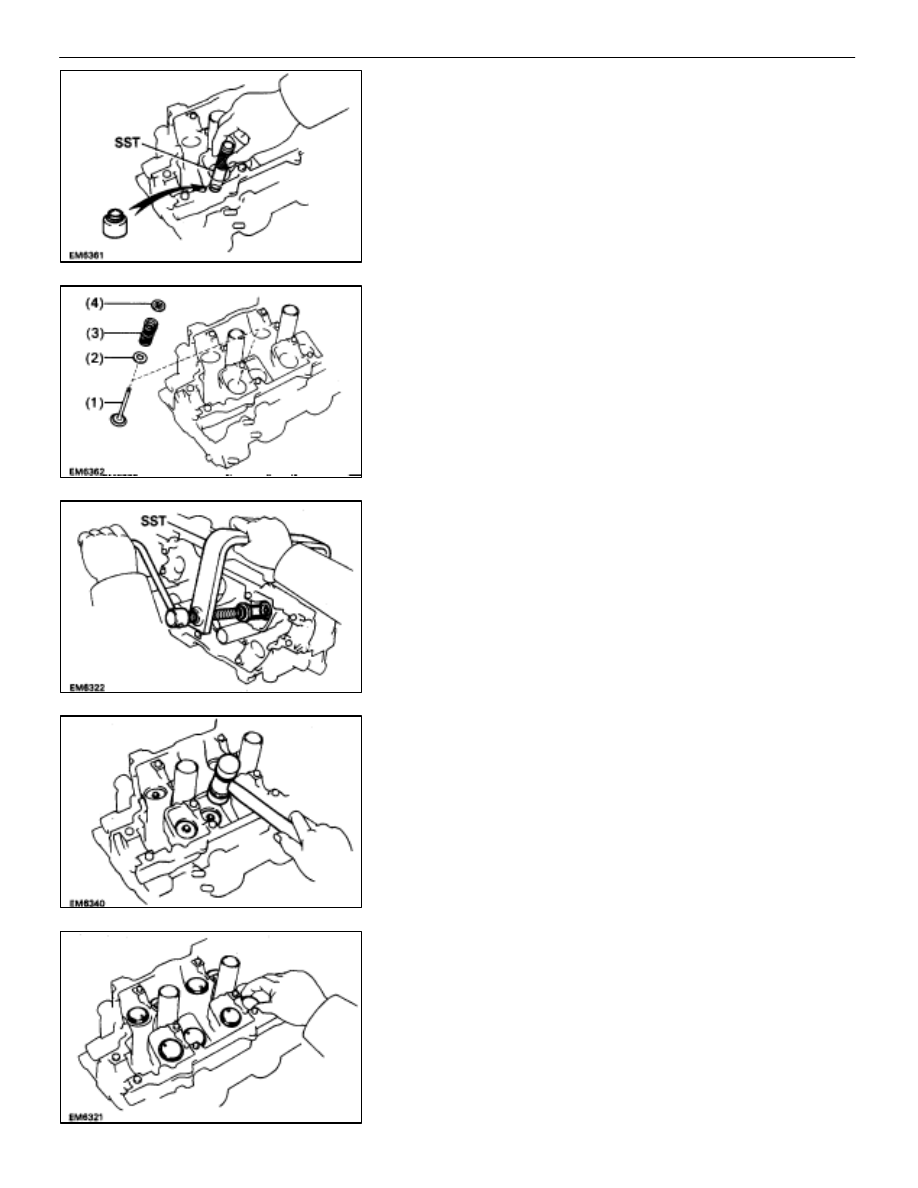
2. INSTALL
VALVES
(a) Using SST, push in a new oil seal.
SST 09201–41020
(b) Install the following parts:
(1)
Valve
(2)
Spring seat
(3)
Valve spring
(4)
Spring retainer
(c) Using
SST,
compress the valve spring and place the two
keepers around the valve stem.
SST 09202–70010
(d) Using a plastic–faced hammer, lightly tap the valve stem
tip to assure proper fit.
3.
INSTALL VALVE LIFTERS AND SHIMS
Check the valve lifter rotates smoothly by hand.
EM–90
–
ENGINE MECHANICAL
Cylinder Heads
Нет комментариевНе стесняйтесь поделиться с нами вашим ценным мнением.
Текст