Lexus SC300 / Lexus SC400. Service manual — part 189
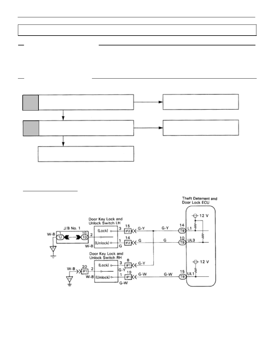
Door Key Lock and Unlock Switch Circuit
CIRCUIT DESCRIPTION
The door key lock and unlock switch is built in the door key cylinder.
When the key is turned to the lock side, terminal 3 of the switch is grounded and when the key is turned
to the unlock side, terminal 1 of the switch is grounded.
DIAGNOSTIC CHART
DIAGNOSTIC CHART
OK
OK
NG
NG
Check door key lock and unlock switch.
Check harness and connectors between ECU
and switch, switch and body ground
(See page
Replace door key lock and unlock
switch.
1
2
Proceed to next circuit inspection shown on
matrix chart (See page
Repair or replace harness or
connector.
WIRING DIAGRAM
BE–386
–
BODY ELECTRICAL SYSTEM
Door Lock Control System
OK
NG
OK
NG
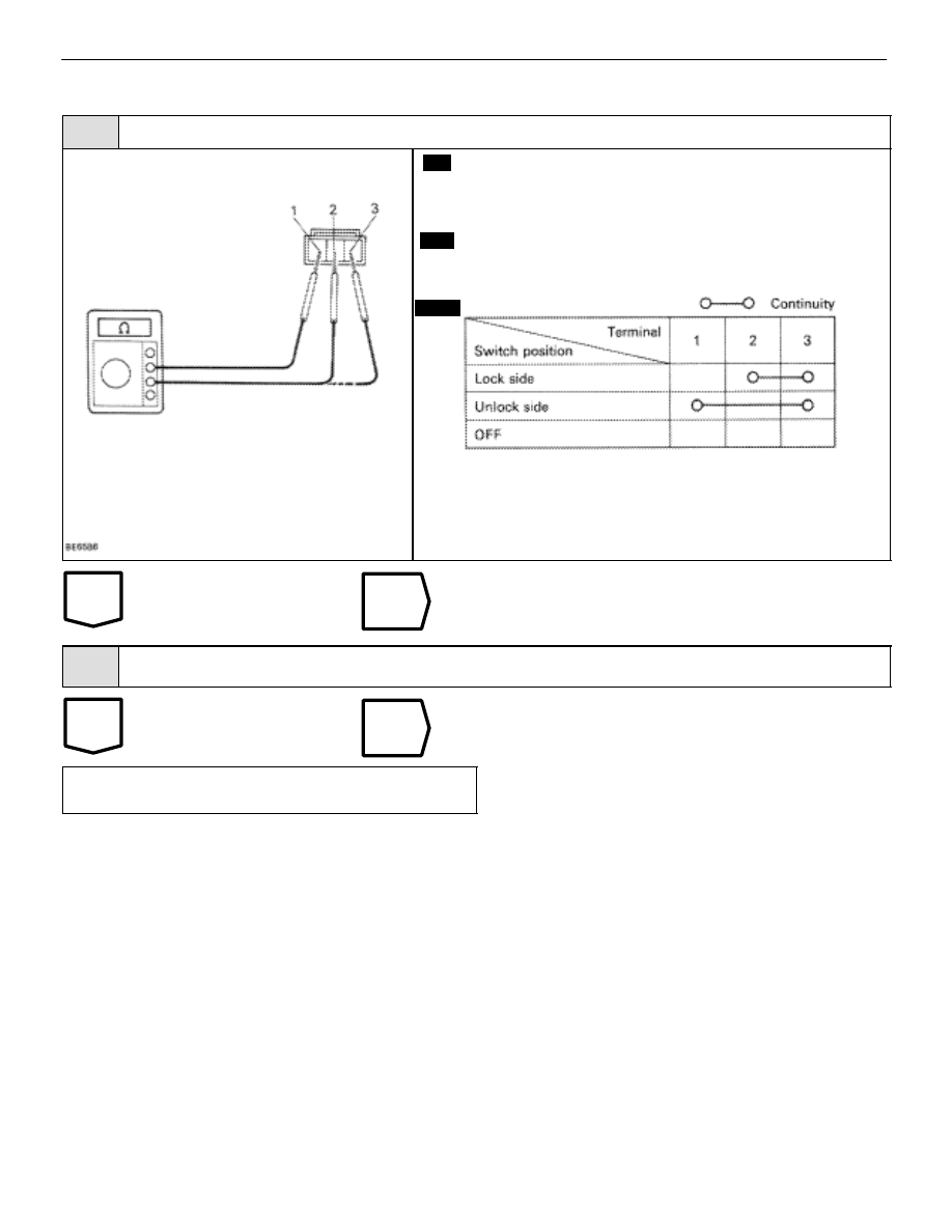
INSPECTION PROCEDURE
1
Check door key lock and unlock switch.
C
OK
P
1.
Remove the door trim and service hole cover.
2.
Disconnect the door ley lock and unlock switch con-
nector.
Check continuity between terminals 1, 2 and 3 of door
key lock and unlock switch is turned to the lock side, un-
lock side and not turned.
Replace door key lock and unlock switch.
2
Check harness and connectors between ECU ans switch, switch and body ground (See page
).
Repair or replace harness or connector.
Proceed to next circuit inspection shown on ma-
trix chart (See page
).
–
BODY ELECTRICAL SYSTEM
Door Lock Control System
BE–387

OK
OK
NG
NG
Check key unlock warning switch.
Check harness and connectors between ECU and
key unlock warning switch, key unlock warning
switch and body ground (See page
Replace key unlock warning
switch.
1
2
Proceed to next circuit inspection shown on
matrix chart (See page
).
Repair or replace harness or
connector.
WIRING DIAGRAM
Key Unlock Warning Switch Circuit
CIRCUIT DESCRIPTION
The key unlock warning switch goes on when the ignition key is inserted in the key cylinder and goes
off when the ignition key is removed.
The ECU operates the key confinement prevention function while the key unlock warning switch is on.
DIAGNOSTIC CHART
DIAGNOSTIC CHART
BE–388
–
BODY ELECTRICAL SYSTEM
Door Lock Control System

OK
NG
OK
NG
INSPECTION PROCEDURE
1
Check key unlock warning switch.
C
OK
P
Disconnect key unlock warning switch connector.
Check continuity between terminal 9 and 10 of key un-
lock warning switch connector, when the key is inserted
to the key cylinder or removed.
Replace key unlock warning switch.
2
Check harness and connectors between ECU and key unlock warning switch, key unlock warn-
ing switch and body ground (See page
Repair or replace harness or connector.
Proceed to next circuit inspection shown on ma-
trix chart (See page
).
–
BODY ELECTRICAL SYSTEM
Door Lock Control System
BE–389
Нет комментариевНе стесняйтесь поделиться с нами вашим ценным мнением.
Текст