Lexus SC300 / Lexus SC400. Service manual — part 502

AIR INDUCTION SYSTEM
Air filtered through the air cleaner passes through the air flow meter and the amount flowing to the air intake
chamber is determined by the throttle valve opening in the throttle body and the engine rpm.
Air flow meter measures the air intake flow to the engine by the swirl frequency.
Located in the throttle body is the throttle valve, which regulates the volume of air intake to the engine. Air
intake controlled by the throttle valve opening is distributed from the intake chamber to the manifold of each
cylinder and is drain into the combustion chamber.
At low air temperature the ISC valve opens and the air flows through the ISC valve, as well as the throttle body,
into the air intake chamber. During engine warm up, the fast idle is accomplished by air flowing into the intake
chamber via ISC valve, even when the throttle valve is completely closed.
The air intake chamber prevents pulsation of the intake air, reduces the influence on the air flow meter and
increases the air intake volume. It also prevents intake air interference in each cylinder.
There is also the Intake Air Control Valve (IACV) attached to the air intake chamber. Part of the Acoustic Control
Induction System (ACIS), the ECU provides signals to the Vacuum Switch Valve (VSV) to open or close. This
valve opens or closes, the vacuum source to the actuator, which in turn opens or closes the IACV. The IACV
is designed to modify the effective manifold length in two stages for increased power in all driving ranges.
–
EFI SYSTEM
Operation
FI–7
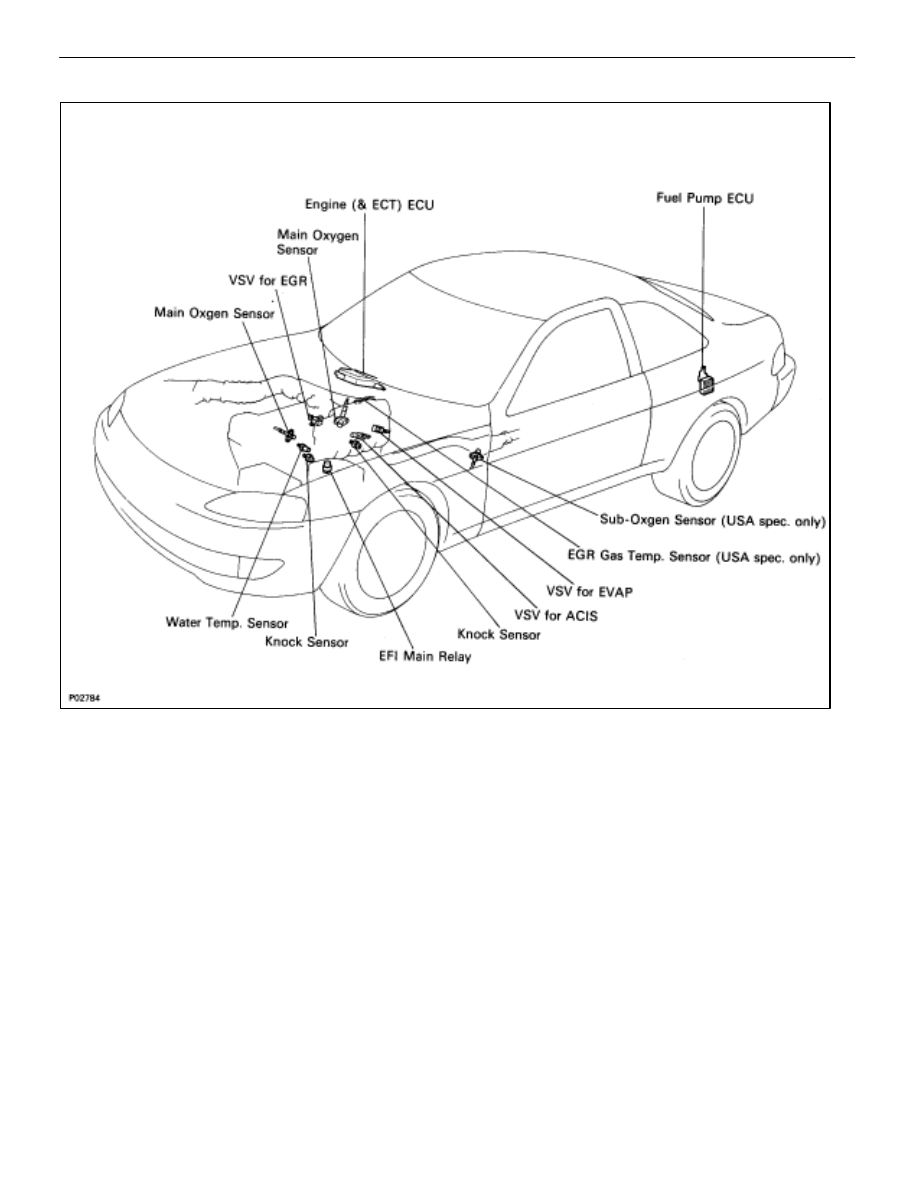
ELECTRONIC CONTROL SYSTEM
The control system consists of sensors which detect various engine conditions, and a ECU which determines
the injection volume (timing) based on the signals from the sensors.
The various sensors detect the air intake volume, engine rpm, oxygen density in the exhaust gas, coolant tem-
perature, air intake temperature and atmospheric pressure etc. and convert the information into an electrical
signal which is sent to the ECU. Based on these signals, the ECU calculates the optimum ignition timing for the
current conditions and operates the injectors.
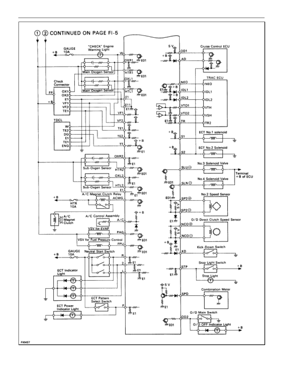
The ECU not only controls the fuel injection timing, but also the self diagnostic function which records the oc-
currence of a malfunction, ignition timing control, idle rpm control, EGR control, EVAP control, ACIS and fuel
pump control, which switches between the high and low fuel pump speeds according to varied load conditions.
FI–8
–
EFI SYSTEM
Operation

OPERATION
FI–5
– Operation
EFI SYSTEM
FI–6
EFI SYSTEM – Operation
Нет комментариевНе стесняйтесь поделиться с нами вашим ценным мнением.
Текст