Lexus SC300 / Lexus SC400. Service manual — part 793
DIAGNOSTIC TROUBLE CODE MATRIX CHART
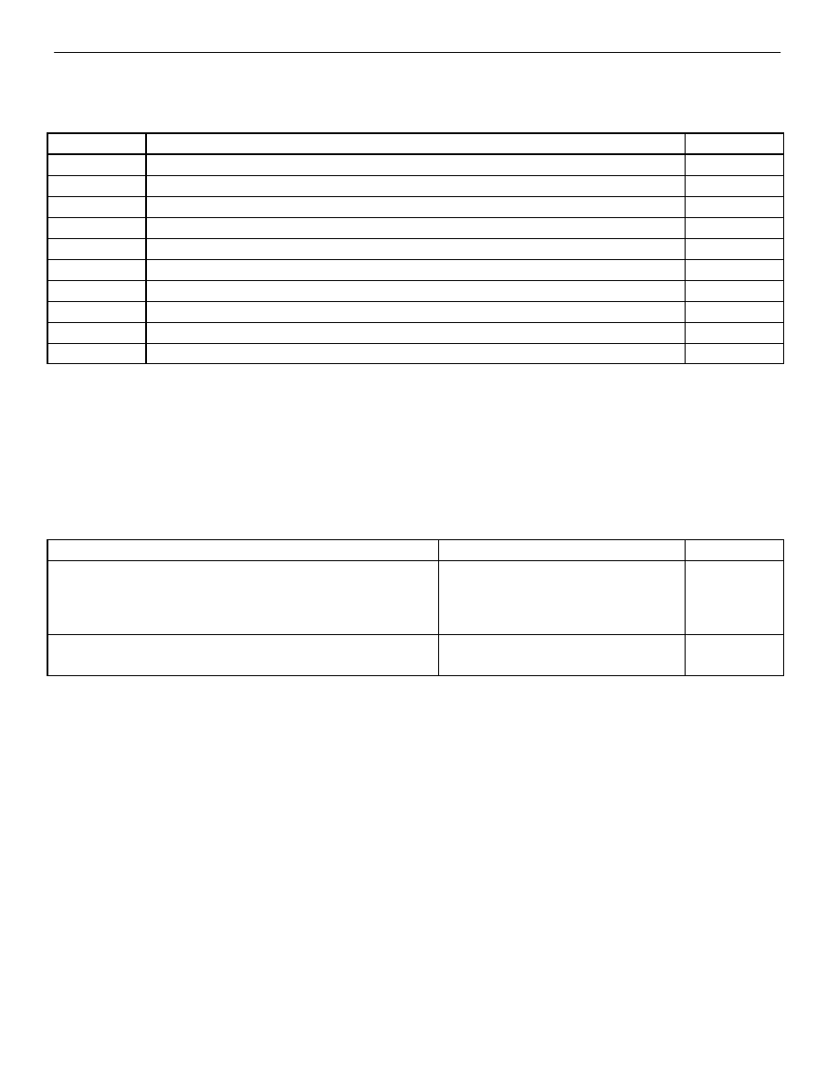
If a malfunction code is displayed during the diagnostic trouble code check, check the circuit listed for that
code in the table below (Proceed to the page given for that circuit).
ÑÑÑÑÑ
ÑÑÑÑÑ
DTC No.
ÑÑÑÑÑÑÑÑÑÑÑÑÑÑÑÑÑÑÑÑÑÑÑÑÑÑÑ
ÑÑÑÑÑÑÑÑÑÑÑÑÑÑÑÑÑÑÑÑÑÑÑÑÑÑÑ
Diagnosis
ÑÑÑÑÑÑ
Page
ÑÑÑÑÑ
ÑÑÑÑÑ
(Normal)*
1
ÑÑÑÑÑÑÑÑÑÑÑÑÑÑÑÑÑÑÑÑÑÑÑÑÑÑÑ
ÑÑÑÑÑÑÑÑÑÑÑÑÑÑÑÑÑÑÑÑÑÑÑÑÑÑÑ
Source voltage drop
ÑÑÑÑÑ
ÑÑÑÑÑ
11
ÑÑÑÑÑÑÑÑÑÑÑÑÑÑÑÑÑÑÑÑÑÑÑÑÑÑÑ
ÑÑÑÑÑÑÑÑÑÑÑÑÑÑÑÑÑÑÑÑÑÑÑÑÑÑÑ
Short in squib circuit or front airbag sensor circuit (to ground)
ÑÑÑÑÑ
ÑÑÑÑÑ
12
ÑÑÑÑÑÑÑÑÑÑÑÑÑÑÑÑÑÑÑÑÑÑÑÑÑÑÑ
ÑÑÑÑÑÑÑÑÑÑÑÑÑÑÑÑÑÑÑÑÑÑÑÑÑÑÑ
Short in squib circuit or front airbag sensor circuit (to B+)
ÑÑÑÑÑ
ÑÑÑÑÑ
13
ÑÑÑÑÑÑÑÑÑÑÑÑÑÑÑÑÑÑÑÑÑÑÑÑÑÑÑ
ÑÑÑÑÑÑÑÑÑÑÑÑÑÑÑÑÑÑÑÑÑÑÑÑÑÑÑ
Short in squib circuit (between D+ wire harness and D– wire harness)
ÑÑÑÑÑ
ÑÑÑÑÑ
14
ÑÑÑÑÑÑÑÑÑÑÑÑÑÑÑÑÑÑÑÑÑÑÑÑÑÑÑ
ÑÑÑÑÑÑÑÑÑÑÑÑÑÑÑÑÑÑÑÑÑÑÑÑÑÑÑ
Open in squib circuit (between D+ wire harness and D– wire harness)
ÑÑÑÑÑ
ÑÑÑÑÑ
15
ÑÑÑÑÑÑÑÑÑÑÑÑÑÑÑÑÑÑÑÑÑÑÑÑÑÑÑ
ÑÑÑÑÑÑÑÑÑÑÑÑÑÑÑÑÑÑÑÑÑÑÑÑÑÑÑ
Open in front airbag sensor circuit
ÑÑÑÑÑ
ÑÑÑÑÑ
22*
2
ÑÑÑÑÑÑÑÑÑÑÑÑÑÑÑÑÑÑÑÑÑÑÑÑÑÑÑ
ÑÑÑÑÑÑÑÑÑÑÑÑÑÑÑÑÑÑÑÑÑÑÑÑÑÑÑ
SRS warning light system malfunction
ÑÑÑÑÑ
ÑÑÑÑÑ
31
ÑÑÑÑÑÑÑÑÑÑÑÑÑÑÑÑÑÑÑÑÑÑÑÑÑÑÑ
ÑÑÑÑÑÑÑÑÑÑÑÑÑÑÑÑÑÑÑÑÑÑÑÑÑÑÑ
Center airbag sensor assembly malfunction
ÑÑÑÑÑ
ÑÑÑÑÑ
53
ÑÑÑÑÑÑÑÑÑÑÑÑÑÑÑÑÑÑÑÑÑÑÑÑÑÑÑ
ÑÑÑÑÑÑÑÑÑÑÑÑÑÑÑÑÑÑÑÑÑÑÑÑÑÑÑ
Short in squib circuit (between P+ wire harness and P– wire harness)
ÑÑÑÑÑ
ÑÑÑÑÑ
54
ÑÑÑÑÑÑÑÑÑÑÑÑÑÑÑÑÑÑÑÑÑÑÑÑÑÑÑ
ÑÑÑÑÑÑÑÑÑÑÑÑÑÑÑÑÑÑÑÑÑÑÑÑÑÑÑ
Open in squib circuit (between P+ wire harness and P– wire harness)
ÑÑÑÑÑÑ
HINT:
*
1
When the SRS warning light remains lit up and the diagnostic trouble code is the normal code, this means
a source voltage drop.
*
2
Code 22 is recorded when a malfunction occurs in the SRS warning light system. If an open malfunction
occurs in the SRS warning light system, the SRS warning light does not light up, so that until the malfunction
is repaired, the diagnostic trouble code (including 22) cannot be confirmed.
PROBLEM SYMPTOM CHART
Proceed with troubleshooting of each circuit in the table below.
ÑÑÑÑÑÑÑÑÑÑÑÑÑÑÑÑÑÑÑ
ÑÑÑÑÑÑÑÑÑÑÑÑÑÑÑÑÑÑÑ
Problem Symptom
ÑÑÑÑÑÑÑÑÑÑÑÑÑ
ÑÑÑÑÑÑÑÑÑÑÑÑÑ
Inspection Item
ÑÑÑÑÑÑ
ÑÑÑÑÑÑ
Page
ÑÑÑÑÑÑÑÑÑÑÑÑÑÑÑÑÑÑÑ
ÑÑÑÑÑÑÑÑÑÑÑÑÑÑÑÑÑÑÑ
ÑÑÑÑÑÑÑÑÑÑÑÑÑÑÑÑÑÑÑ
With the ignition switch at ACC or ON, the SRS warning light
sometimes lights up after approx. 6 seconds have elapsed
SRS warning light system
(Always lit up when ignition switch is
ÑÑÑÑÑÑÑÑÑÑÑÑÑÑÑÑÑÑÑ
ÑÑÑÑÑÑÑÑÑÑÑÑÑÑÑÑÑÑÑ
ÑÑÑÑÑÑÑÑÑÑÑÑÑÑÑÑÑÑÑ
SRS warning light lights up even when ignition switch is in
the LOCK position
(Always lit up when ignition switch is
LOCK position)
ÑÑÑÑÑÑÑÑÑÑÑÑÑÑÑÑÑÑÑ
ÑÑÑÑÑÑÑÑÑÑÑÑÑÑÑÑÑÑÑ
Diagnostic trouble code not displayed.
Tc terminal circuit
ÑÑÑÑÑÑÑÑÑÑÑÑÑÑÑÑÑÑÑ
ÑÑÑÑÑÑÑÑÑÑÑÑÑÑÑÑÑÑÑ
Diagnostic trouble code continuously displayed.
Tc terminal circuit
–
SUPPLEMENTAL RESTRAINT SYSTEM
TROUBLESHOOTING
RS–67

WIRING DIAGRAM
CIRCUIT INSPECTION
DTC
(Normal) Source Voltage Drop
CIRCUIT DESCRIPTION
The supplemental restraint system is equipped with a voltage – increase circuit (DC–DC converter) in the center
airbag sensor assembly in case the source voltage drops.
When the battery voltage drops, the voltage – increase circuit (DC–DC converter) functions to increase the volt-
age of the supplemental restraint system to normal voltage.
The diagnosis system malfunction display for this circuit is different to other circuits – when the SRS warning
light remains lit up and the diagnostic trouble code is a normal code, source voltage drop is indicated. Malfunc-
tion in this circuit is not recorded in the center airbag sensor assembly, and approx. 10 seconds after the source
voltage returns to normal, the SRS warning light automatically goes off.
DTC No.
Diagnosis
(Normal)
Source voltage drop.
DIAGNOSTIC CHART
DIAGNOSTIC CHART
).
RS–68
–
SUPPLEMENTAL RESTRAINT SYSTEM
TROUBLESHOOTING

YES
NO
INSPECTION PROCEDURE
1
Preparation.
P
1.
Turn ignition switch LOCK.
2.
Disconnect battery negative (–) terminal cable, and
wait at least 90 seconds.
3.
Connect battery negative (–) terminal cable.
4.
Disconnect center airbag sensor assembly con-
nector.
5.
Turn ignition switch ON. But do not start engine.
6.
Measure voltage at IG
2
or ACC on connector wire
harness side of center airbag sensor assembly and
operate electric system (defogger, wiper, headlight,
heater blower, etc.)
Voltage: 6 V – 11.5 V at IG
2
and ACC.
7.
Turn electric system switch OFF.
8.
Turn ignition switch LOCK.
9.
Disconnect battery negative (–) terminal cable, and
wait at least 90 seconds.
10. Remove voltmeter and connect center airbag sen-
sor assembly connector.
11. Connect battery negative (–) terminal cable.
2
Does SRS warning light turn off after approx. 10 seconds?
C
P
Turn ignition switch ACC or ON and wait at least 20 sec-
onds.
Clear malfunction code. Turn ignition switch LOCK and
wait at least 20 seconds.
Operate electric system checked in
(5) and check
that SRS warning light goes off after approx. 10 sec-
onds.
Check diagnostic trouble code, and if a malfunction code
is output, perform trouble shooting according to mal-
function code. If a normal code is output, replace center
airbag sensor assembly.
Check battery and charging system.
(See page
–
SUPPLEMENTAL RESTRAINT SYSTEM
TROUBLESHOOTING
RS–69

DTC
11
Short in Squib Circuit or Front Airbag Sen-
sor Circuit (to Ground)
CIRCUIT DESCRIPTION
The squib circuit consists of the center airbag sensor assembly, spiral cable and the steering wheel pad (squib),
wire harness connector and front passenger airbag assembly (squib). It causes the SRS to operate when the
SRS operation conditions are satisfied.
The front airbag sensor detects the deceleration force in a frontal collision and is located in the front fender on
the left and right sides.
For details of the function of each component, see FUNCTION OF COMPONENTS on page
trouble code 11 is recorded when occurrence of ground short is detected in the squib circuit or front airbag sen-
sor circuit.
DTC No.
Diagnosis
11
Short circuit in squib wire harness (to ground)
Squib malfunction
Short circuit in front airbag sensor +S, D
+
, D–, P+, P– wire harness (to ground).
Front airbag sensor malfunctions.
Short circuit between +S wire harness and –S wire harness of front airbag sensor.
Spiral cable malfunction.
Center airbag sensor assembly malfunction.
RS–70
–
SUPPLEMENTAL RESTRAINT SYSTEM
TROUBLESHOOTING
Нет комментариевНе стесняйтесь поделиться с нами вашим ценным мнением.
Текст