Lexus SC300 / Lexus SC400. Service manual — part 21
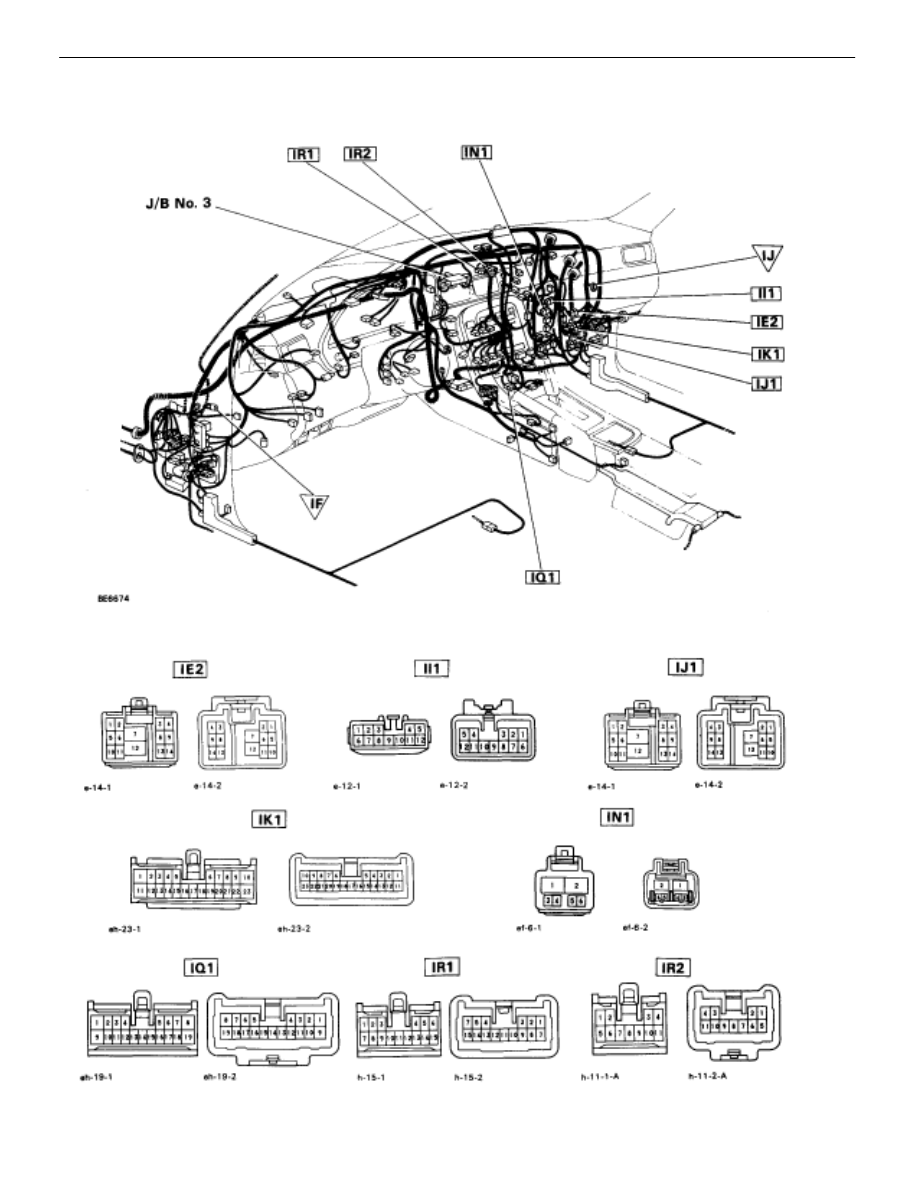
LOCATION OF CONNECTORS IN INSTRUMENT PANEL
AC–42
–
AIR CONDITIONING SYSTEM
Troubleshooting

–
AIR CONDITIONING SYSTEM
Troubleshooting
AC–43
Check voltage between terminals TR
and SG of air conditioner assembly
connector.
Check room temperature sensor.
Check harness and connector between air
conditioner control assembly and room tem-
perature sensor (See page
Check and repair air conditioner control
assembly.
Proceed to next circuit inspection
shown on matrix chart (See page
).However, when Diag. code
11 is displayed, check and replace
air conditioner control assembly.
Replace room temperature sensor.
Repair or replace harness or
connector.
CIRCUIT INSPECTION
Diag. Code 11
Room Temperature Sensor Circuit
CIRCUIT DESCRIPTION
This sensor detects the temperature inside the cabin and sends the appropriate signals the A/C control
assembly.
Code No.
Diag. Code Detecting Condition
Trouble area
11
Open or short in room temperature sensor
circuit.
Room temperature sensor.
Harness or connector between room temp.
sensor and A/C control assembly.
A/C control assembly.
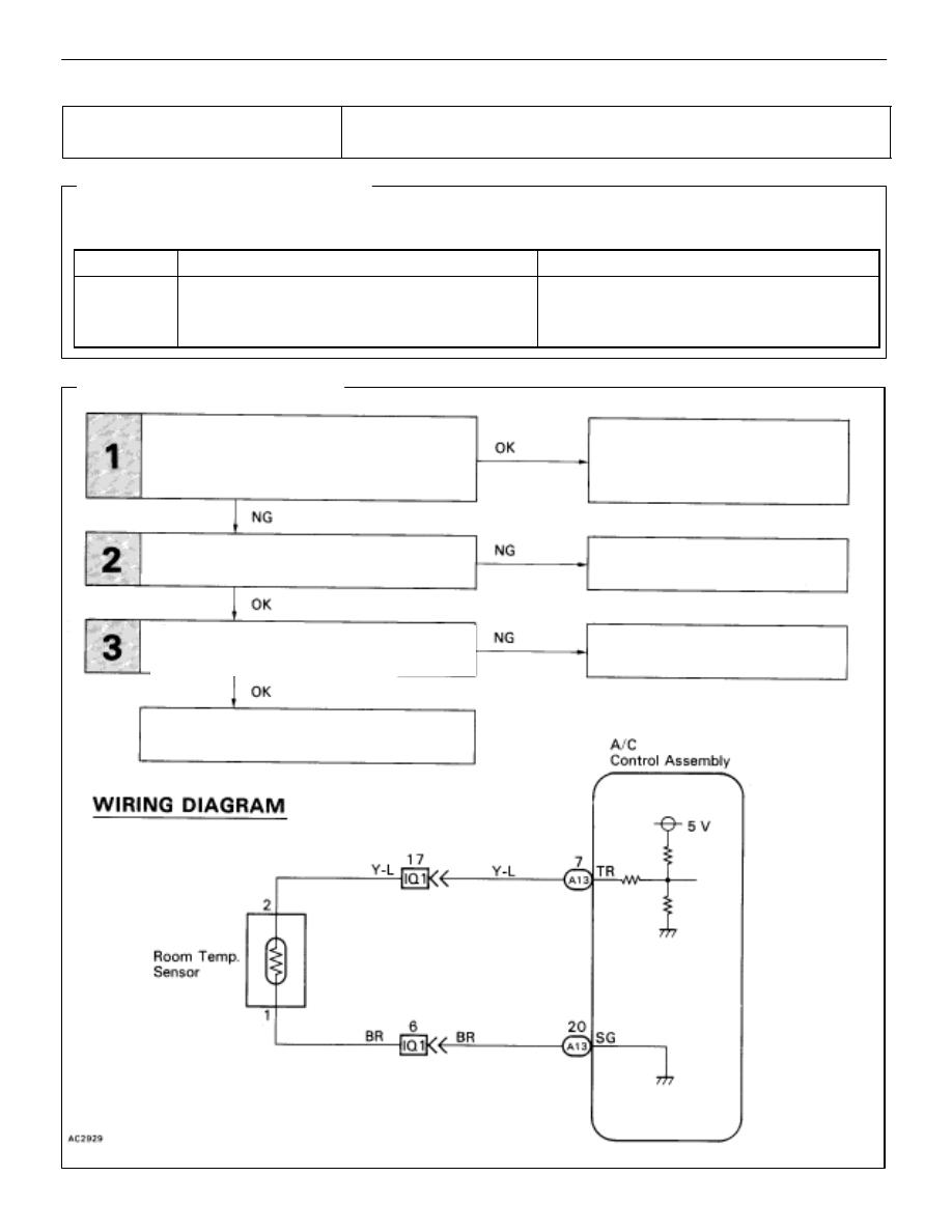
DIAGNOSTIC CHART
AC–44
–
AIR CONDITIONING SYSTEM
Troubleshooting

Check voltage between terminals TR and SG of air conditioner control
assembly connector.
(1)
Remove console upper panel. (See page
)
(2)
Remove A/C Control Assembly with connectors
still connected.
(3)
Turn ignition switch ON.
Check voltage between terminals TAM and SG of air
conditioner control assembly connector at each tem-
perature.
Voltage
at 25
°
C (77
°
F) : 1.8~2.2 V
at 40
°
C (104
°
F) : 1.2~1.6 V
In addition, as the temperature increases, the
voltage decreases gradually.
Proceed to next circuit inspection shown on
matrix chart (See page
when Diag. code 11 is displayed, check and
replace air conditioner control assembly.
Check room temperature sensor.
(1)
Remove instrument finish lower No. 1 panel.
(See page
Resistance
at 25
°
C (77
°
F) : 1.6~1.8k
at 50
°
C (122
°
F) : 0.5~0.7k
In addition, as the temperature increases, the
voltage decreases gradually.
Replace room temperature sensor.
Check for open and short in harness and connector between air conditioner
control assembly and room temperature sensor (See page
Repair or replace harness or connector.
Check and repair air conditioner control
assembly.
(2)
Disconnect room0 temperature sensor
connector.
Check voltage between terminals 1 and 2 of
room temperature sensor connector at each tem–
perature.
INSPECTION PROCEDURE
–
AIR CONDITIONING SYSTEM
Troubleshooting
AC–45
Нет комментариевНе стесняйтесь поделиться с нами вашим ценным мнением.
Текст