Lexus SC300 / Lexus SC400. Service manual — part 729
INSTALLATION OF STARTER
(See Components on page
)
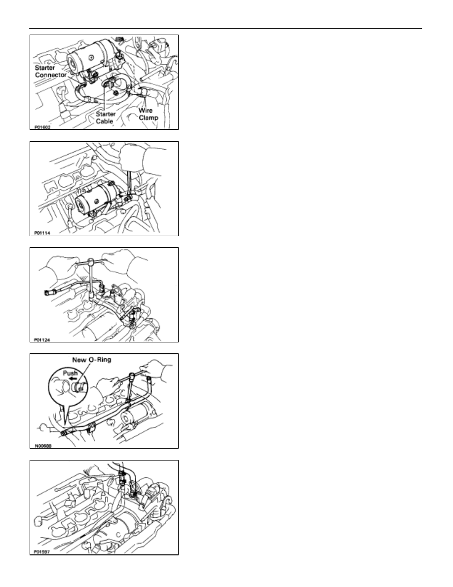
1. INSTALL
STARTER
(a) Connect the wire clamp to the wire bracket.
(b) Connect the starter wire with the nut.
(c) Connect the starter connector.
(d) Install the starter with the two bolts.
Torque: 39 N
⋅
m (400 kgf
⋅
cm, 29 ft
⋅
lbf)
2.
INSTALL REAR WATER BY–PASS JOINT
(a) Install
four new gaskets and the water by–pass joint with
the four nuts.
Torque: 18 N
⋅
m (185 kgf
⋅
cm, 13 ft
⋅
lbf)
(b) Install the bolt holding the water by–pass pipe to the LH
engine hanger.
3. INSTALL
WATER
BY–PASS
PIPE
(a) Install a new O–ring to the water by–pass pipe.
(b) Apply soapy water to the O–ring.
(c) Push in the water by–pass pipe end into the pipe hole
of the water pump.
(d) Install the water by–pass pipe with the two bolts.
Torque: 18 N
⋅
m (185 kgf
⋅
cm, 13 ft
⋅
lbf)
4. CONNECT HEATER WATER HOSES TO WATER
BY–PASS PIPE AND REAR WATER BY–PASS JOINT
–
STARTING SYSTEM
Starter
ST–25
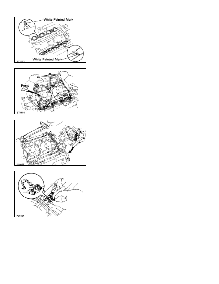
5. INSTALL
DELIVERY
PIPES
AND
INTAKE
MANIFOLD
ASSEMBLY
(a) Place two new gaskets on the cylinder heads with the
white painted mark facing upward.
NOTICE: Align the port holes of the gasket and cylinder
head. Be careful of the installation direction.
(b) Place the delivery pipes and intake manifold assembly
in position on the cylinder heads with the arrow mark on
the intake manifold facing forward.
NOTICE: Be careful of the installation direction.
(c) Install the six mounting bolts and four mounting nuts.
Torque: 18 N
⋅
m (185 kgf
⋅
cm, 13 ft
⋅
lbf)
HINT: Use bolts 30 mm (1.18 in.) in length.
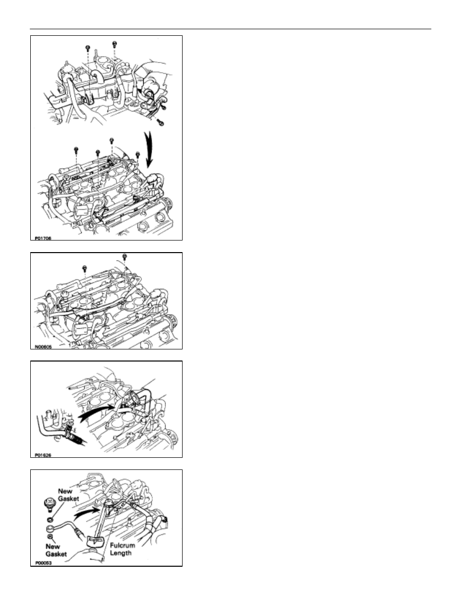
6.
INSTALL FUEL RETURN PIPE
Install the return pipe with two new gaskets, union bolt and
bolt.
Torque (Union bolt):
35 N
⋅
m (360 kgf
⋅
cm, 26 ft
⋅
lbf)
7. INSTALL ENGINE WIRE TO DELIVERY PIPES, REAR
WATER BY–PASS JOINT AND RH CYLINDER HEAD
(a) Connect the eight injector connectors.
(b) Connect the two engine wire connectors to the
connector bracket on the LH delivery pipe.
ST–26
–
STARTING SYSTEM
Starter
(c) Install the engine wire to the RH cylinder head with the
two bolts.
(d) Install the engine wire to the rear water by–pass joint
with the two bolts.
(e) Install the engine wire to the delivery pipes with the four
bolts.
8.
INSTALL ENGINE WIRE TO INTAKE MANIFOLD
Install the engine wire with the two bolts.
9. TEMPORARILY INSTALL EGR PIPE TO RH CYLINDER
HEAD
Temporarily install the EGR pipe with the bolt.
10. CONNECT
FUEL RETURN HOSE TO FUEL RETURN PIPE
11. CONNECT FUEL INLET HOSE TO LH DELIVERY PIPE
Using SST, connect the inlet hose with two new gaskets and
pulsation damper.
SST 09612–24014 (09617–24011)
Torque: 39 N
⋅
m (400 kgf
⋅
cm, 29 ft
⋅
lbf)
33 N
⋅
m (340 kgf
⋅
cm, 24 ft
⋅
lbf) for SST
HINT: Use a torque wrench with a fulcrum length of 30 cm
(11.81 in.).
–
STARTING SYSTEM
Starter
ST–27
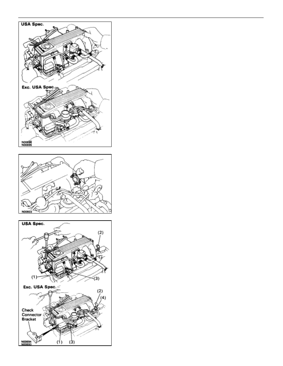
12. INSTALL AIR INTAKE CHAMBER
(a) Place four new gaskets and the air intake chamber on
the intake manifold.
(b) Temporarily
install a new gasket and the EGR pipe to air
intake chamber with the two bolts.
(c) (Exc. USA Spec.)
Install the connector bracket to check (”DIAGNOSIS”)
connector.
(d) Install the air intake chamber and following parts with
the four bolts and eight nuts:
(1) Check (”DIAGNOSIS”) connector
(2) A/T throttle cable bracket
(3) VSV for fuel pressure control system
(4) VSV for EGR system
Torque: 18 N
⋅
m (185 kgf
⋅
cm, 13 ft
⋅
lbf)
HINT: Use bolts 40 mm (1.57 in.) of length.
ST–28
–
STARTING SYSTEM
Starter
Нет комментариевНе стесняйтесь поделиться с нами вашим ценным мнением.
Текст