Lexus SC300 / Lexus SC400. Service manual — part 638

(c) Check the ignition timing.
Ignition timing: 8–12
°
BTDC @ idle
(Transmission in neutral range)
If the ignition timing is not as specified, check that following
conditions are normal:
•
Throttle valve fully closed
•
Continuity between terminals IDL1 and E2 of the
throttle position sensor (See page
)
•
(e) Remove the SST from the check connector.
SST 09843–18020
17. DISCONNECT TACHOMETER AND TIMING LIGHT FROM
ENGINE
18. INSTALL UPPER HIGH–TENSION CORD COVER
(See step 10 on pages
–
IGNITION SYSTEM
Distributor
IG–29

ENGINE SPEED SENSOR
COMPONENTS FOR REMOVAL AND
INSTALLATION
REMOVAL OF ENGINE SPEED SENSOR
1.
DISCONNECT CABLE FROM NEGATIVE TERMINAL OF
BATTERY
CAUTION: Work must be started after approx. 20 se-
conds or longer from the time the ignition switch is
turned to the ”LOCK” position and the negative (–) termi-
nal cable is disconnected from the battery.
2.
REMOVE ENGINE UNDER COVER
3.
DISCONNECT ENGINE SPEED SENSOR CONNECTOR
4.
REMOVE ENGINE SPEED SENSOR
Remove the bolt and engine speed sensor.
INSTALLATION OF ENGINE SPEED
SENSOR
1.
INSTALL ENGINE SPEED SENSOR
Torque: 6.4 N
⋅
m (65 kgf
⋅
cm, 56 in.
⋅
lbf)
2.
CONNECT ENGINE SPEED SENSOR CONNECTOR
3.
INSTALL ENGINE UNDER COVER
4. CONNECT CABLE TO NEGATIVE TERMINAL OF
BATTERY
IG–30
–
IGNITION SYSTEM
Engine Speed sensor
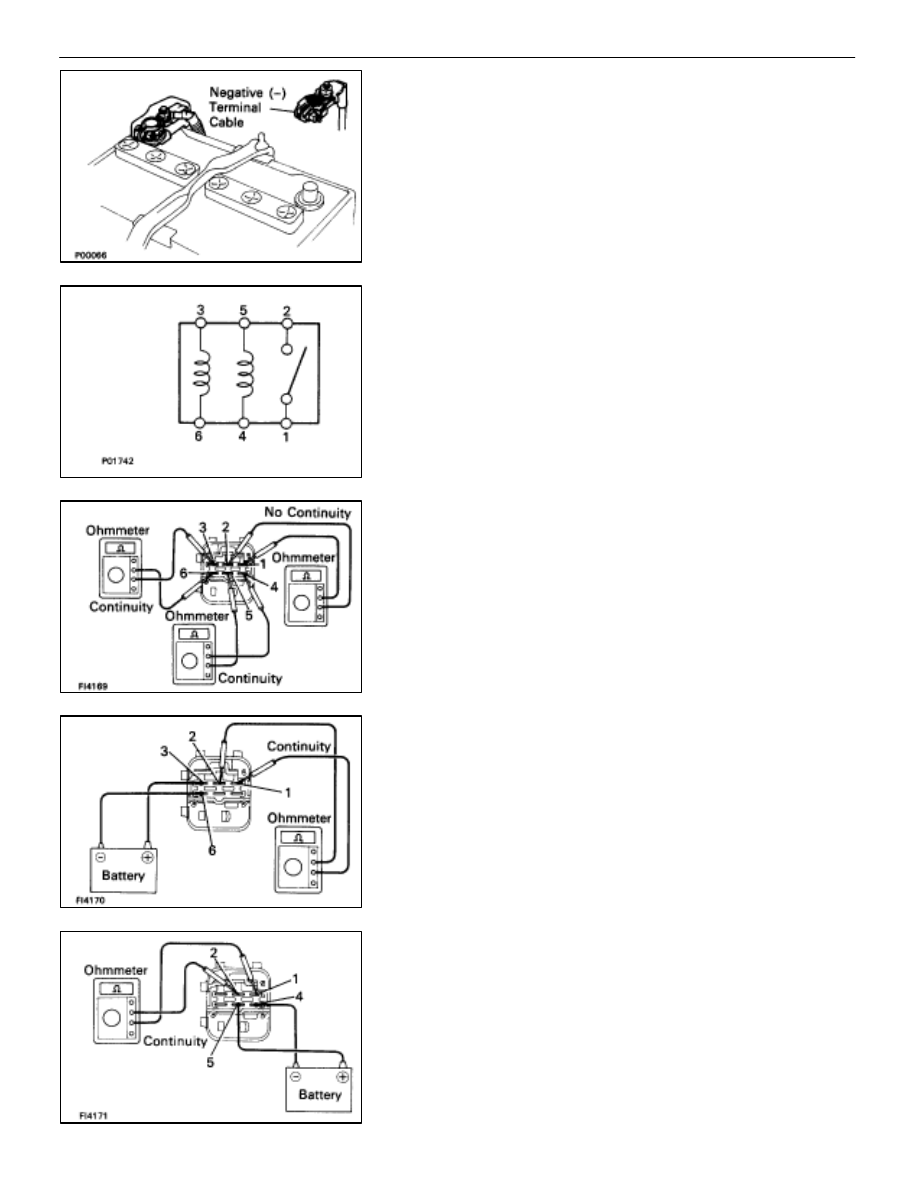
IGNITION MAIN RELAY
INSPECTION OF IGNITION MAIN RELAY
1.
DISCONNECT CABLE FROM NEGATIVE TERMINAL OF
BATTERY
CAUTION: Work must be started after approx. 20 se-
conds or longer from the time the ignition switch is
turned to the ”LOCK” position and the negative (–) termi-
nal cable is disconnected from the battery.
2.
REMOVE IGNITION MAIN RELAY
LOCATION: In the engine compartment relay box.
3.
INSPECT IGNITION MAIN RELAY
A. Inspect relay continuity
(a) Using an ohmmeter, check that there is continuity
between terminals 3 and 6.
(b) Check that there is continuity between terminals 4 and
5.
(c) Check that there is no continuity between terminals 1
and 2.
If continuity is not as specified, replace the relay.
B. Inspect relay operation
(a) Apply battery voltage across terminals 3 and 6.
(b) Using an ohmmeter, check that there is continuity
between terminals 1 and 2.
(c) Apply battery voltage across terminals 4 and 5.
(d) Using an ohmmeter, check that there is continuity
between terminals 1 and 2.
If operation is not as specified, replace the relay.
4.
REINSTALL IGNITION MAIN RELAY
5. RECONNECT CABLE TO NEGATIVE TERMINAL OF
BATTERY
–
IGNITION SYSTEM
Ignition Main Relay
IG–31

SERVICE SPECIFICATIONS
SERVICE DATA
Ignition timing
8–12
°
BTDC @ idle
g
g
(w/ Terminals TE1 and E1 connected)
Firing order
1–8–4–3–6–5–7–2
Spark plug
Type
ND
PK20R11
g
NGK
BKR6EP11
Electrode gap
New plug
STD
1.1 mm
0.043 in.
Used plug
Limit
1.3 mm
0.051 in.
High–tension
Resistance
25 k
per cord
g
cord
Ignition coil
Primary coil resistance
0.40–0.50
g
y
Secondary coil resistance
10.0–14.0 k
Cam position
Resistance
at –10– +40
°
C (14–104
°
F)
835–1,350
sensor
Engine speed
Resistance
at –10– +40
°
C (14–104
°
F)
835–1,350
sensor
TORQUE SPECIFICATIONS
Part tightened
N
⋅
m
kgf
⋅
cm
ft
⋅
lbf
Spark plug X Cylinder head
18
180
13
Cam position sensor X Distributor housing
18
185
13
Distributor cap X Distributor housing
3.8
39
34 in.
⋅
lbf
Distributor rotor X Camshaft timing pulley
3.8
39
34 in.
⋅
lbf
RH No.2 timing belt cover X Cylinder block (for 12 mm head)
16
160
12
Drive belt idler pulley X Hydraulic pump
37
380
27
Engine speed sensor X Oil pump
6.4
65
56 in.
⋅
lbf
IG–32
–
IGNITION SYSTEM
Service Specifications
Нет комментариевНе стесняйтесь поделиться с нами вашим ценным мнением.
Текст