Lexus SC300 / Lexus SC400. Service manual — part 522

SERVICE SPECIFICATIONS
SERVICE DATA
Ignition timing
8–12
°
BTDC @ idle
g
g
(w/ Terminals TE1 and E1 connected)
Firing order
1–8–4–3–6–5–7–2
Spark plug
Type
ND
PK20R11
g
NGK
BKR6EP11
Electrode gap
New plug
STD
1.1 mm
0.043 in.
Used plug
Limit
1.3 mm
0.051 in.
High–tension
Resistance
25 k
per cord
g
cord
Ignition coil
Primary coil resistance
0.40–0.50
g
y
Secondary coil resistance
10.0–14.0 k
Cam position
Resistance
at –10– +40
°
C (14–104
°
F)
835–1,350
sensor
Engine speed
Resistance
at –10– +40
°
C (14–104
°
F)
835–1,350
sensor
TORQUE SPECIFICATIONS
Part tightened
N
⋅
m
kgf
⋅
cm
ft
⋅
lbf
Spark plug X Cylinder head
18
180
13
Cam position sensor X Distributor housing
18
185
13
Distributor cap X Distributor housing
3.8
39
34 in.
⋅
lbf
Distributor rotor X Camshaft timing pulley
3.8
39
34 in.
⋅
lbf
RH No.2 timing belt cover X Cylinder block (for 12 mm head)
16
160
12
Drive belt idler pulley X Hydraulic pump
37
380
27
Engine speed sensor X Oil pump
6.4
65
56 in.
⋅
lbf
IG–32
–
IGNITION SYSTEM
Service Specifications
IGNITION SYSTEM
IG–1
IGNITION SYSTEM
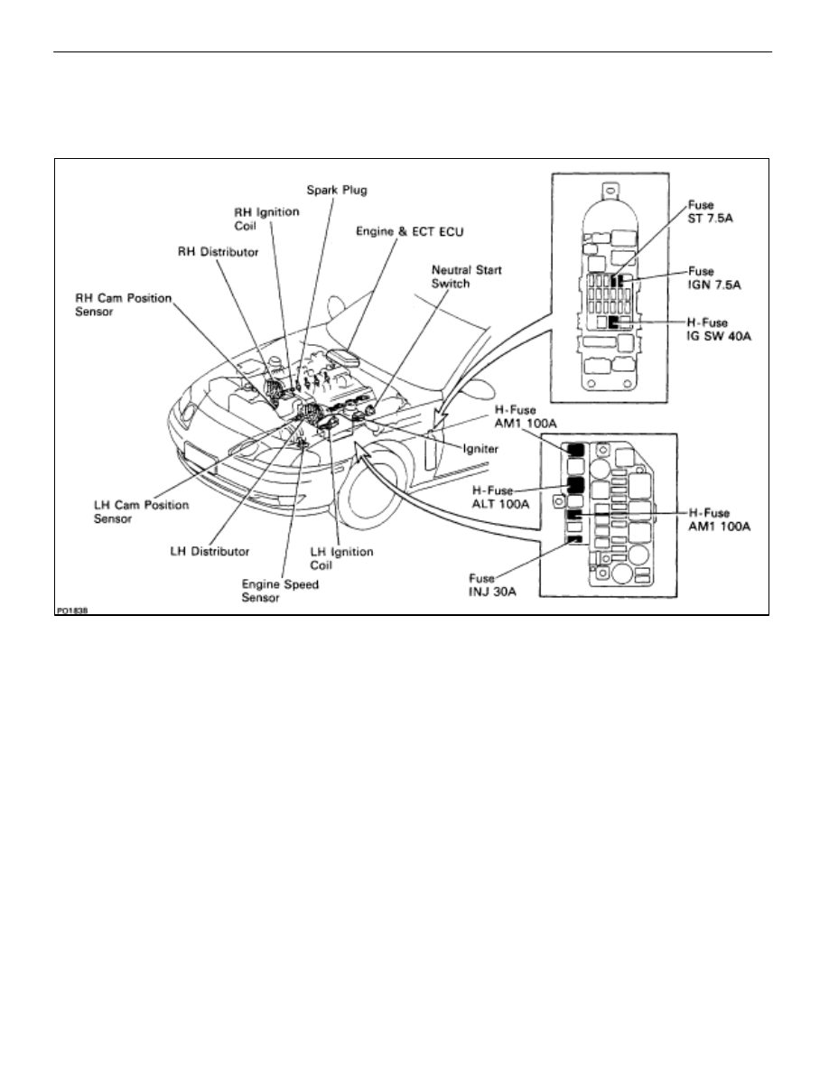
DESCRIPTION
The ECU is programmed with data for optimum ignition timing under any and all operating conditions. Using
data provided by sensors which monitor various engine functions (rpm, intake air volume, engine temperature,
etc.) the microcomputer (ECU) triggers the spark at precisely the right instant.
The ECU monitors the engine condition by signals from each sensor, calculates the ignition timing and sends
an ignition signal to the igniter. High voltage from the ignition is distributed to each spark plug in the appropriate
order to generate a spark between the electrodes, which ignites the air–fuel mixture.
IGNITERS
The igniter temporarily interrupts the primary current with the ignition signal (IGT signal) from the ECU and
generates sparks at the spark plug. Also, as a fail–safe measure, when ignition occurs, an ignition confirmation
signal (IGF signal) is sent to the ECU.
IGNITION COIL
The ignition coil uses a closed core coil with the primary coil wrapped around the core and the secondary
coil wrapped around the primary coil. This allows the generation of a high voltage sufficient to cause a spark
to jump across the spark plug gap.
DISTRIBUTORS
This correctly distributes high voltage to the spark plug of each cylinder in the specified ignition order.
ENGINE SPEED SENSOR
The engine speed sensor detects the crank angle.
CAM POSITION SENSORS
The RH and LH cam position sensors detect the cam angle.
IG–2
–
IGNITION SYSTEM
Description
PRECAUTIONS
1. Do not leave the ignition switch on for more than 10
minutes if the engine will not start.
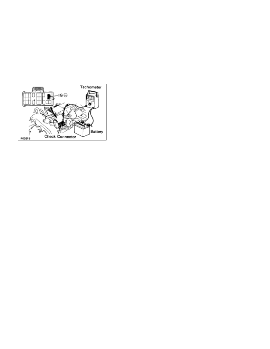
2.
With a tachometer connected to the system, connect the
tester probe of the tachometer to terminal IG È of the
check (”DIAGNOSIS”) connector.
HINT:
•
Allow the engine to warm up to normal operation
temperature.
•
Set the tachometer to the 4–cylinder range.
3. As some tachometers are not compatible with this
ignition system, we recommend that you confirm the
compatibility of your unit before use.
4.
Never allow the tachometer terminal to touch ground as
this could damage the igniter and/or ignition coil.
5. Do not disconnect the battery when the engine is
running.
6.
Check that the igniter is properly grounded to the body.
–
IGNITION SYSTEM
Precautions
IG–3
Нет комментариевНе стесняйтесь поделиться с нами вашим ценным мнением.
Текст