Lexus SC300 / Lexus SC400. Service manual — part 527

SERVICE SPECIFICATIONS
SERVICE DATA
Ignition
T/M in N range
10
°
BTDC @ idle
timing
[Check connector terminals TE1 and E1 con-
nect]
Spark plug
Type
ND
PK16R11
NGK
BKR5EP11
GAP
STD
1.1 mm
0.043 in.
Limit
1.3 mm
0.051 in.
High–tension
Resistance
Limit
25 k
Ω
per cord
cord
Ignition coil
Primary coil resistance
0.2–0.3
Secondary coil resistance
6–11 k
Distributor
Air gaps
0.2–0.4 mm
0.008–0.016 in.
Pickup coil resistance (cold)
G1–G (–)
125–190
Ω
G2–G (–)
125–190
Ω
NE–G (–)
155–240
Ω
–
IGNITION SYSTEM
Service Specifications
IG–15
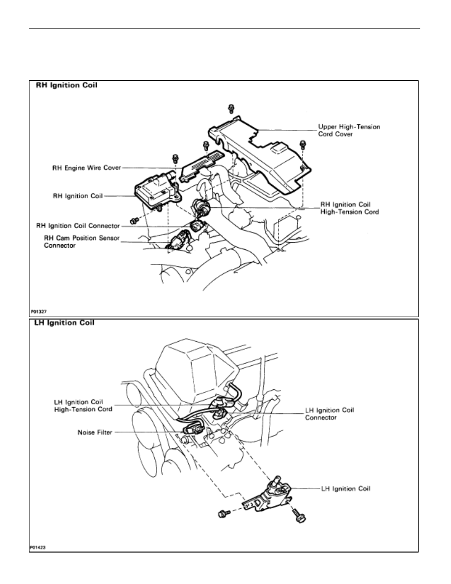
IGNITION COILS
COMPONENTS FOR REMOVAL AND
INSTALLATION
IG–20
–
IGNITION SYSTEM
Ignition Coils
REMOVAL OF RH IGNITION COIL
(See Components on page
)
1.
REMOVE RH ENGINE WIRE COVER
(See steps 1, 3 and 4 on pages
and 12)
2.
DISCONNECT HIGH–TENSION CORD
(See step 9 on pages
3.
DISCONNECT IGNITION COIL CONNECTOR
4.
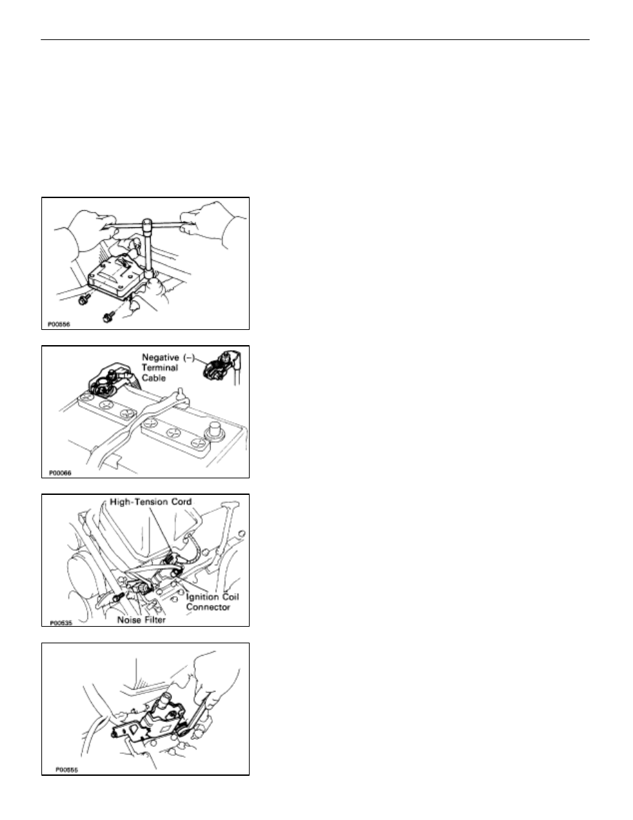
REMOVE IGNITION COIL
(a) Remove
the three bolts, and disconnect the ignition coil.
(b) Disconnect the cam position sensor connector, and
remove the ignition coil.
REMOVAL OF LH IGNITION COIL
(See Components on page
)
1.
DISCONNECT CABLE FROM NEGATIVE TERMINAL OF
BATTERY
CAUTION: Work must be started after approx. 20 se-
conds or longer from the time the ignition switch is
turned to the ”LOCK” position and the negative (–) termi-
nal cable is disconnected from the battery.
2.
DISCONNECT IGNITION COIL CONNECTOR
3.
DISCONNECT HIGH–TENSION CORD
(See step 9 on pages
4.
DISCONNECT NOISE FILTER FROM IGNITION COIL
Remove the bolt, and disconnect the noise filter.
5.
REMOVE IGNITION COIL
Remove the two bolts and ignition coil.
–
IGNITION SYSTEM
Ignition Coils
IG–21
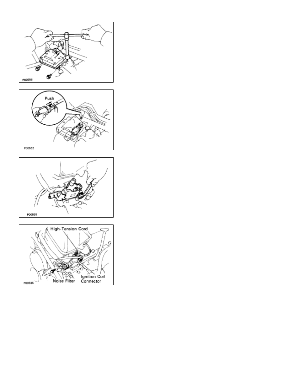
INSTALLATION OF RH IGNITION COIL
(See Components on page
)
1.
INSTALL IGNITION COIL
(a) Install the ignition coil with the three bolts.
(b) Install the cam position sensor connector to the ignition
coil bracket.
2.
CONNECT IGNITION COIL CONNECTOR
3.
CONNECT HIGH–TENSION CORD
(See step 4 on pages
4.
INSTALL RH ENGINE WIRE COVER
(See steps 8, 10, 12 and 13 on pages
INSTALLATION OF LH IGNITION COIL
(See Components on page
)
1.
INSTALL IGNITION COIL
Install the ignition coil with the two bolts.
2.
INSTALL NOISE FILTER TO IGNITION COIL
Install the noise filter with the bolt.
3.
CONNECT HIGH–TENSION CORD
(See step 4 on pages
4.
CONNECT IGNITION COIL CONNECTOR
5. CONNECT CABLE TO NEGATIVE TERMINAL OF
BATTERY
IG–22
–
IGNITION SYSTEM
Ignition Coils
Нет комментариевНе стесняйтесь поделиться с нами вашим ценным мнением.
Текст