Lexus SC300 / Lexus SC400. Service manual — part 761
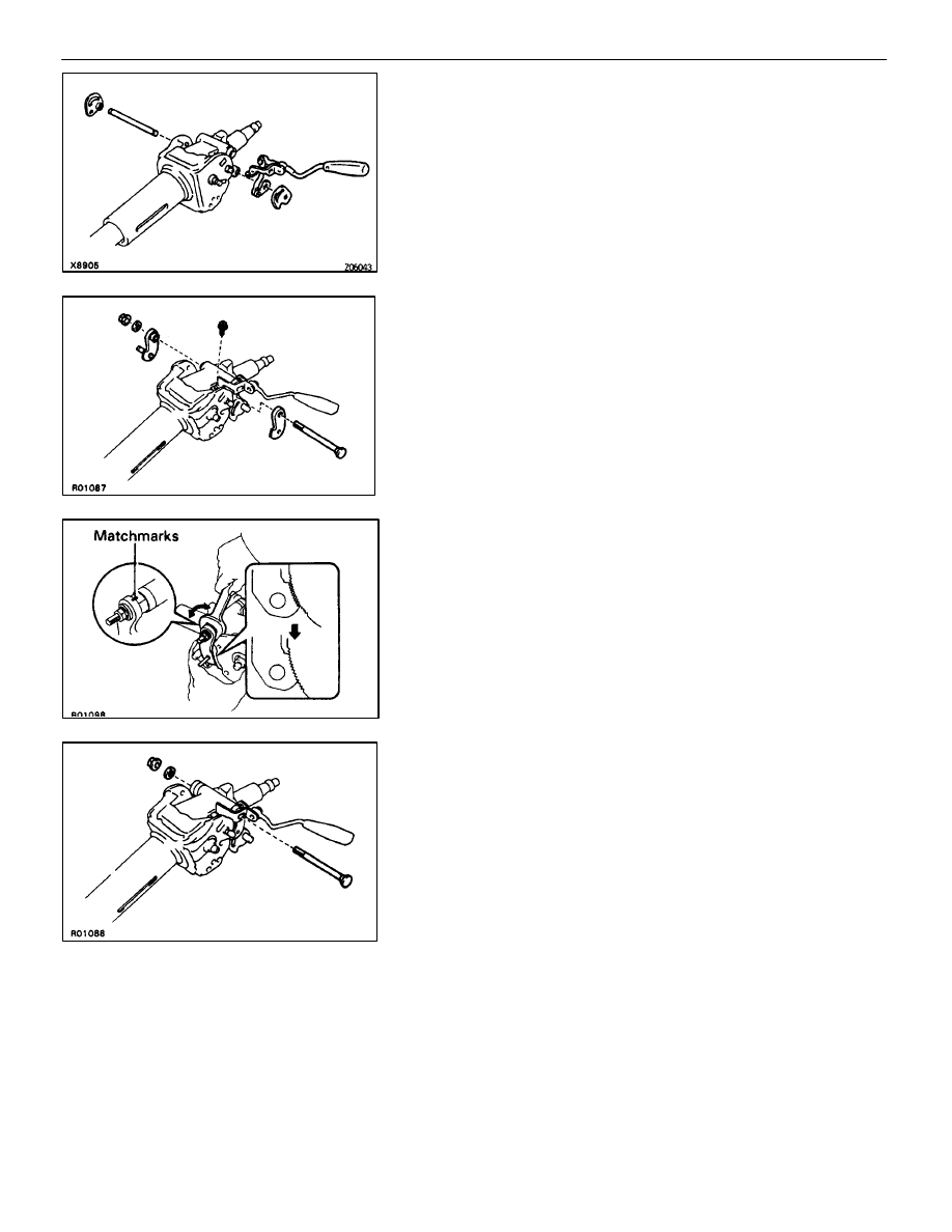
6. INSTALL TILT LEVER LOCK SHAFT, TILT LEVER
ASSEMBLY, TILT SUB LEVER AND TILT LEVER
(a) Install the tilt lever lock shaft into the upper column tube.
(b) Install the tilt lever assembly.
(c) Install the tilt lever and tilt sub lever.
7. INSTALL
TILT
PAWLS
(a) Install the 2 tilt pawls to the upper column tube.
HINT: Install the pawl pin into the long hole of the tilt lever and
tilt sub lever.
(b) Install the bolt through the tilt pawls and tilt lever assembly.
(c) Temporarily install the washer and nut.
(d) Install and torque the tilt lever assembly installation bolt.
Torque: 2.9 N
⋅
m (30 kgf
⋅
cm, 26 in.
⋅
lbf)
8.
ENGAGE AND ADJUST TILT PAWL
(a) Engage
the tilt sub lever side pawl to the center of the ratchet.
(b) While turning the tilt lever side collar, completely engage the
tilt lever side pawl to the ratchet.
(c) Place matchmarks on the pawl and collar.
(d) Remove the nut and washer.
(e) Pull out the bolt.
–
STEERING
STEERING COLUMN
SR–21

9.
SELECT 2 PAWL STOPPERS
(a) With the tilt pawl and ratchet engaged, install the 2 pawl
stoppers.
(b) Check that the alignment marks on the stopper and pawl
align when the stopper is lightly rotated to the pawl side.
(c) If the alignment marks do not align, select pawl stoppers
according to the following table.
ÑÑÑÑÑÑÑ
ÑÑÑÑÑÑÑ
ÑÑÑÑÑÑÑ
Tilt lever side
ÑÑÑÑÑÑÑ
ÑÑÑÑÑÑÑ
ÑÑÑÑÑÑÑ
Tilt sub lever side
ÑÑÑÑÑÑÑÑÑ
ÑÑÑÑÑÑÑÑÑ
ÑÑÑÑÑÑÑÑÑ
Dimension “A”
mm (in.)
ÑÑÑÑÑÑÑ
ÑÑÑÑÑÑÑ
ÑÑÑÑÑÑÑ
1
ÑÑÑÑÑÑÑ
ÑÑÑÑÑÑÑ
ÑÑÑÑÑÑÑ
A
ÑÑÑÑÑÑÑÑÑ
ÑÑÑÑÑÑÑÑÑ
ÑÑÑÑÑÑÑÑÑ
12.68 – 12.74
(0.4992 – 0.5016)
ÑÑÑÑÑÑÑ
ÑÑÑÑÑÑÑ
ÑÑÑÑÑÑÑ
2
ÑÑÑÑÑÑÑ
ÑÑÑÑÑÑÑ
ÑÑÑÑÑÑÑ
B
ÑÑÑÑÑÑÑÑÑ
ÑÑÑÑÑÑÑÑÑ
ÑÑÑÑÑÑÑÑÑ
12.61–12.67
(0.4965 – 0.4988)
ÑÑÑÑÑÑÑ
ÑÑÑÑÑÑÑ
ÑÑÑÑÑÑÑ
3
ÑÑÑÑÑÑÑ
ÑÑÑÑÑÑÑ
ÑÑÑÑÑÑÑ
C
ÑÑÑÑÑÑÑÑÑ
ÑÑÑÑÑÑÑÑÑ
ÑÑÑÑÑÑÑÑÑ
12.54 – 12.60
(0.4937 – 0.4961)
ÑÑÑÑÑÑÑ
ÑÑÑÑÑÑÑ
ÑÑÑÑÑÑÑ
4
ÑÑÑÑÑÑÑ
ÑÑÑÑÑÑÑ
ÑÑÑÑÑÑÑ
D
ÑÑÑÑÑÑÑÑÑ
ÑÑÑÑÑÑÑÑÑ
ÑÑÑÑÑÑÑÑÑ
12.47 – 12.53
(0.4909– 0.4933)
ÑÑÑÑÑÑÑ
ÑÑÑÑÑÑÑ
ÑÑÑÑÑÑÑ
5
ÑÑÑÑÑÑÑ
ÑÑÑÑÑÑÑ
ÑÑÑÑÑÑÑ
E
ÑÑÑÑÑÑÑÑÑ
ÑÑÑÑÑÑÑÑÑ
ÑÑÑÑÑÑÑÑÑ
12.40 – 12.46
(0.4882 – 0.4906)
ÑÑÑÑÑÑÑ
ÑÑÑÑÑÑÑ
ÑÑÑÑÑÑÑ
6
ÑÑÑÑÑÑÑ
ÑÑÑÑÑÑÑ
ÑÑÑÑÑÑÑ
F
ÑÑÑÑÑÑÑÑÑ
ÑÑÑÑÑÑÑÑÑ
ÑÑÑÑÑÑÑÑÑ
12.33 – 12.39
(0.4854 – 0.4878)
ÑÑÑÑÑÑÑ
ÑÑÑÑÑÑÑ
ÑÑÑÑÑÑÑ
7
ÑÑÑÑÑÑÑ
ÑÑÑÑÑÑÑ
ÑÑÑÑÑÑÑ
G
ÑÑÑÑÑÑÑÑÑ
ÑÑÑÑÑÑÑÑÑ
ÑÑÑÑÑÑÑÑÑ
12.26 – 12.32
(0.4827 – 0.4850)
(d) After selecting the stoppers, check that on both sides the
pawl and ratchet are fully engaged.
10. INSTALL 2 PAWL STOPPERS AND 2 TILT LEVER
RETAINERS
(a) Install the tilt sub lever side pawl stopper and retainer.
(b) Install the spacer and new E–ring.
(c) Install the nut to the tilt steering bolt.
Torque: 15 N
⋅
m (150 kgf
⋅
cm, 11 ft
⋅
lbf)
(d) Install the collar to the tilt memory bolt.
(e) Install the nut to the tilt memory bolt.
Torque: 5.9 N
⋅
m (60 kgf
⋅
cm, 52 in.
⋅
lbf)
(f)
Install the tilt lever side pawl stopper and tilt lever retainer.
(g) Install the E–ring.
(h) Install and torque the nut.
Torque: 15 N
⋅
m (150 kgf
⋅
cm, 11 ft
⋅
lbf)
SR–22
–
STEERING
STEERING COLUMN

11. INSTALL
BOLT
(a) Tighten the nut with the matchmarks on the pawl and collar
are aligned.
Torque: 5.9 N
⋅
m (60 kgf
⋅
cm, 52 in.
⋅
lbf)
(b) Check that the pawls rotate smoothly.
12. INSTALL 3 TENSION SPRINGS
13. INSTALL COMPRESSION SPRING
(a) Install the 2 bushings to the spring.
(b) Install the spring and bolt.
(c) Using a torx wrench, tighten the bolt.
Torx wrench: T30 (Part No. 09042–00010 or locally manufac-
tured tool)
Torque: 7.8 N
⋅
m (80 kgf
⋅
cm, 69 in.
⋅
lbf)
14. INSTALL 2 LOCK WEDGES TO BREAKAWAY BRACKET
NOTICE: Make sure that no grease gets on the contact
surface between the lock wedge and the lower column
tube.
15. INSTALL
BREAKAWAY
BRACKET
(a) Install the steering shaft thrust stopper.
(b) Install the breakaway bracket to the main shaft.
Be careful that the spline part of the main shaft does not sep-
arate.
–
STEERING
STEERING COLUMN
SR–23

(c) Using snap ring pliers, install the snap ring to the main shaft.
(d) Install the steering column tube stopper bolt.
Torque: 19 N
⋅
m (195 kgf
⋅
cm, 14 ft
⋅
lbf)
16. INSTALL TELESCOPIC LEVER LOCK BOLT
(a) Pull the steering column tube away from the breakaway
bracket and facing the body installation surface of the
breakaway bracket upward, temporarily install the lock bolt.
(b) Install a double nut on the lock bolt.
Torque to 16 N
⋅
m (160 kgf
⋅
cm, 12 ft
⋅
lbf), loosen once, then
torque again to 7.4 N
⋅
m (75 kgf
⋅
cm, 65 in.
⋅
lbf).
17. INSTALL TELESCOPIC LEVER
(a) Install the compression spring and ball.
(b) Install the washer, lever, collar and bolt.
Torque: 25 N
⋅
m (260 kgf
⋅
cm, 19 ft
⋅
lbf)
18. INSTALL TELESCOPIC LEVER SERRATION
ATTACHMENT
(a) Rotate the telescopic lever until it touches the breakaway
bracket.
(b) Install the serration attachment so that the alignment marks
on the telescopic lever and the serration attachment align.
Torque: 13 N
⋅
m (130 kgf
⋅
cm, 9 ft
⋅
lbf)
SR–24
–
STEERING
STEERING COLUMN
Нет комментариевНе стесняйтесь поделиться с нами вашим ценным мнением.
Текст