Lexus SC300 / Lexus SC400. Service manual — part 273
OK
NG
OK
NG
INSPECTION PROCEDURE
1
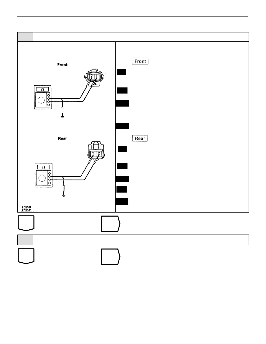
Check speed sensor.
C
OK
P
OK
C
P
OK
C
OK
1.
Remove front fender liner.
2.
Disconnect speed sensor connector.
Measure resistance between terminals 1 and 2 of speed
sensor connector.
Resistance:
0.6 – 1.8 k
Measure resistance between terminals 1 and 2 of speed
sensor connector and body ground.
Resistance:
1 M
or higher
1.
Remove rear fender liner.
2.
Disconnect speed sensor connector.
Measure resistance between terminals 1 and 2 of speed
sensor connector.
Resistance:
0.6 – 1.7 k
Measure resistance between terminals 1 and 2 of speed
sensor connector.
Resistance:
1 M
or higher
Replace speed sensor.
2
Check for open and short in harness and connector between each speed sensor and ECU (See
page
Repair or replace harness or connector.
BR–120
–
BRAKE SYSTEM
ANTI–LOCK BRAKE SYSTEM (ABS)
OK
NG
3
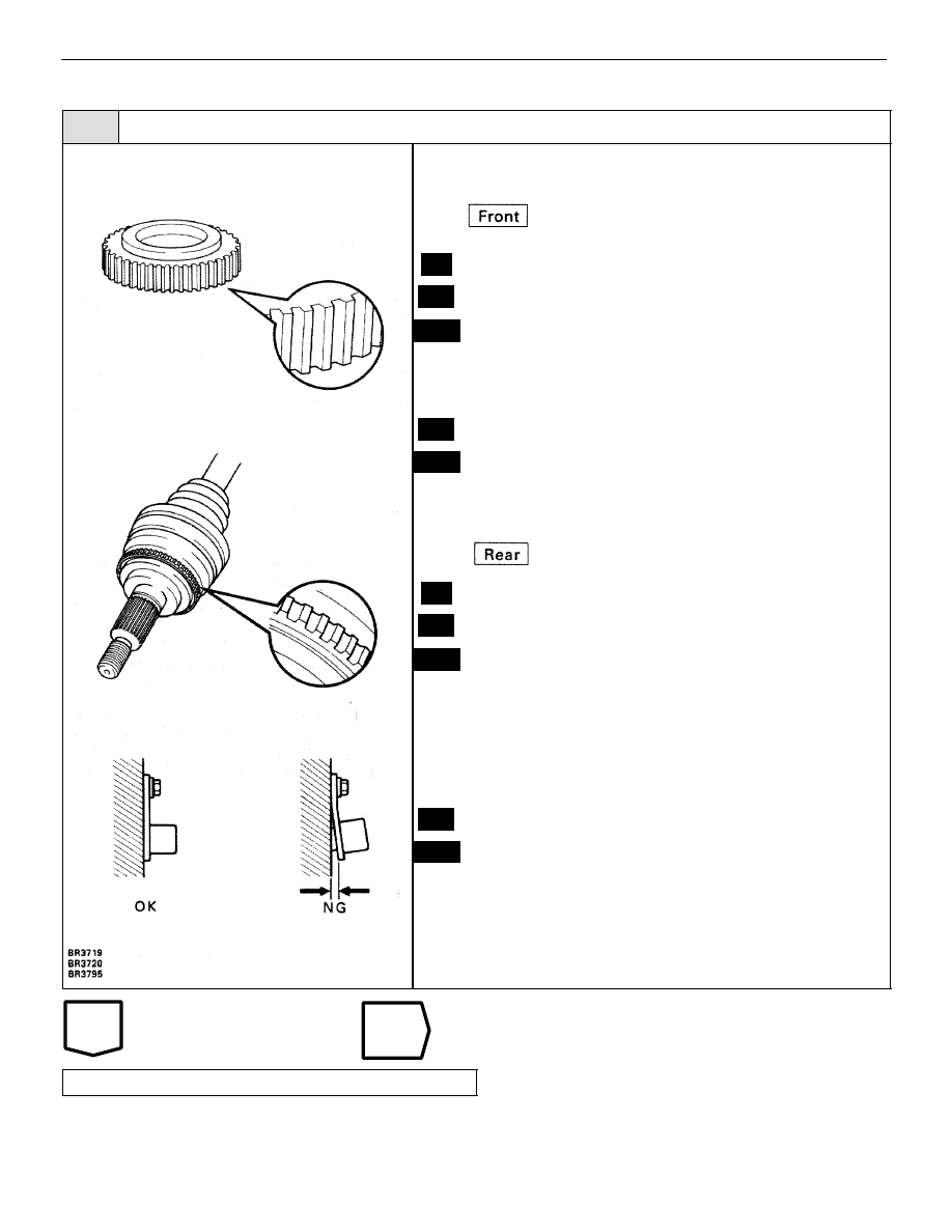
Check sensor rotor and sensor installation.
C
OK
P
C
OK
C
OK
P
C
OK
Remove front speed sensor rotor (See page
Check sensor rotor serrations.
No scratches or missing teeth.
Check the front speed sensor installation.
The installation bolt is tightened properly.
Remove the drive shaft (See page
Check the sensor rotor serrations.
No scratches or missing teeth.
Check the rear speed sensor installation.
The installation bolt is tightened properly and there
is no clearance between the sensor and rear axle
carrier.
Replace speed sensor or rotor.
Check and replace ABS (& TRAC) ECU.
–
BRAKE SYSTEM
ANTI–LOCK BRAKE SYSTEM (ABS)
BR–121

WIRING DIAGRAM
DTC
41
IG Power Source Circuit
CIRCUIT DESCRIPTION
This is the power source for the ECU and becomes the power source for the CPU and actuators.
DTC No.
DTC Detecting Condition
Trouble Area
41
Vehicle speed is 3 km/h (1.9 mph) or moreand voltage
of ECU terminal IG remains at
more than 17V or below
9.5V for more than
10 sec.
Battery
IC regulator
Open or short in power source circuit
ECU
Fail safe function: If trouble occurs in the power source circuit, the ECU cuts off current to the ABS
solenoid relay and prohibits ABS control.
DIAGNOSTIC CHART
DIAGNOSTIC CHART
BR–122
–
BRAKE SYSTEM
ANTI–LOCK BRAKE SYSTEM (ABS)
OK
NG
NG
OK
INSPECTION PROCEDURE
1
Check battery positive voltage.
Voltage:
10 – 14 V
OK
Check and repair the charging system.
2
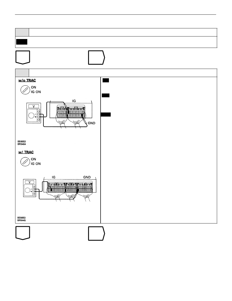
Check voltage between terminals IG1 and GND or ABS (& TRAC) ECU connector.
C
OK
P
Remove ABS (& TRAC) ECU with connectors still con-
nected.
1.
Turn ignition switch on.
2.
Measure voltage between terminals IG1 and GND
of ABS (& TRAC) ECU connector.\
Voltage:
10 – 14 V
Check and replace ABS (& TRAC) ECU.
–
BRAKE SYSTEM
ANTI–LOCK BRAKE SYSTEM (ABS)
BR–123
Нет комментариевНе стесняйтесь поделиться с нами вашим ценным мнением.
Текст