Lexus SC300 / Lexus SC400. Service manual — part 820
FRONT AXLE HUB
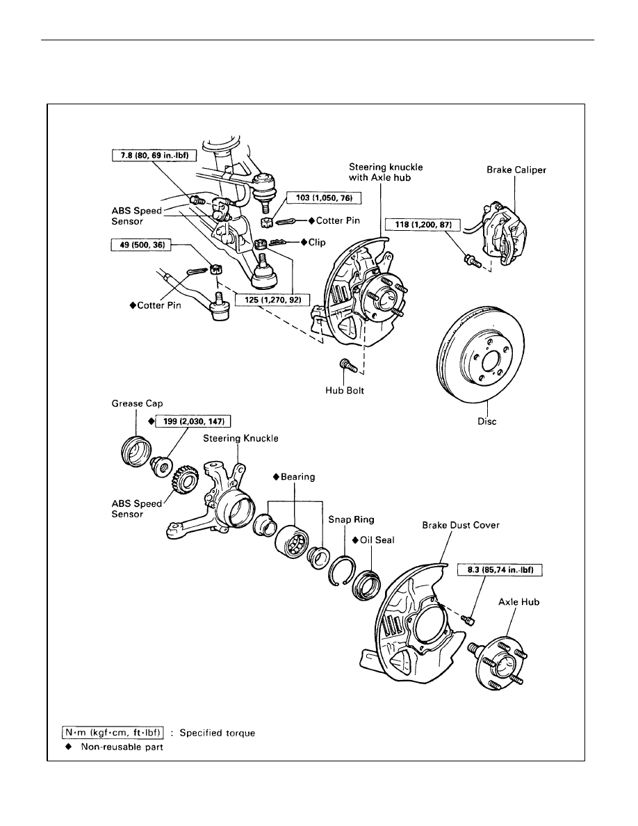
COMPONENTS
SA003–0B
SA–16
–
SUSPENSION AND AXLE
FRONT AXLE HUB
STEERING KNUCKLE WITH AXLE HUB
REMOVAL
SA01Y–08
1.
JACK UP VEHICLE AND REMOVE FRONT WHEEL
2.
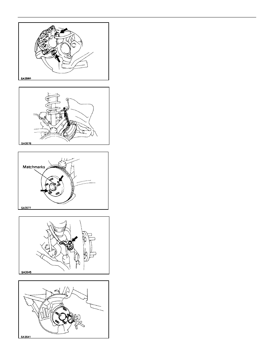
REMOVE FRONT BRAKE CALIPER AND BRAKE DISC
(a) Remove the 2 bolts and remove the brake caliper from the
steering knuckle.
(b) Hang up the brake caliper using wire, etc.
(c) Place matchmarks on the brake disc and axle hub.
(d) Remove the 2 screws and remove the brake disc.
3. REMOVE
ABS
SPEED
SENSOR
FROM
STEERING
KNUCKLE
Remove the bolt and disconnect the sensor from the steering
knuckle.
4.
CHECK BACKLASH IN BEARING SHAFT DIRECTION
Place the dial indicator near the center of the axle hub and
check the backlash in the bearing shaft direction.
Maximum:
0.05 mm (0.0020 in.)
If greater than the specified maximum, replace the bearing.
–
SUSPENSION AND AXLE
FRONT AXLE HUB
SA–17

5.
CHECK AXLE HUB DEVIATION
Using a dial indicator, check the deviation at the surface of
the axle hub outside the hub bolt.
Maximum:
0.05 mm (0.0020 in.)
If greater than the specified maximum, replace the axle hub.
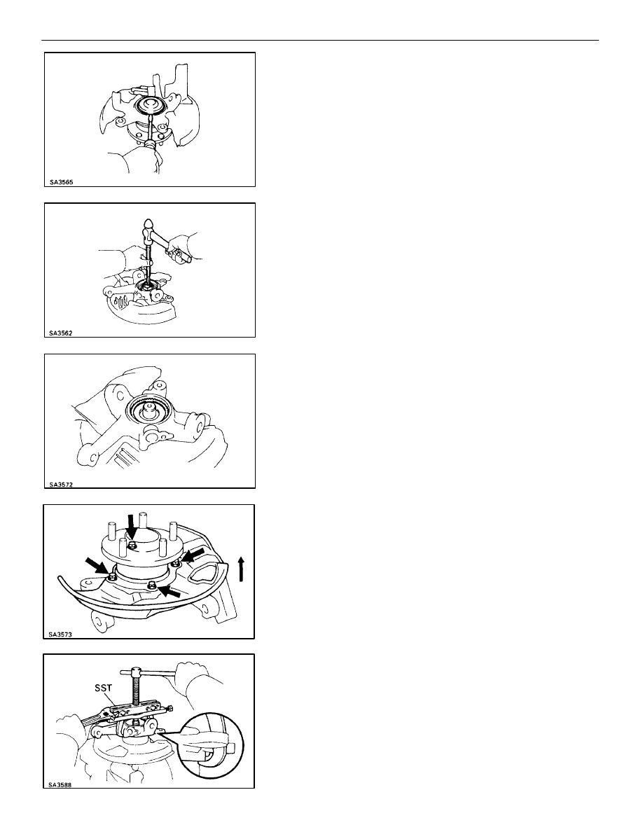
6. DISCONNECT TIE ROD END FROM STEERING
KNUCKLE
(a) Remove the cotter pin and nut.
(b) Using SST, disconnect the tie rod end from the steering
knuckle.
SST 09628–10011
7. DISCONNECT
STEERING
KNUCKLE
FROM
UPPER
SUSPENSION ARM
(a) Remove the cotter pin and nut.
(b) Using SST, disconnect the steering knuckle from the upper
suspension arm.
SST 09628–62011
8.
REMOVE STEERING KNUCKLE
(a) Remove the clip and nut.
(b) Using SST, remove the steering knuckle from the lower
suspension arm.
SST 09628–62011
SA–18
–
SUSPENSION AND AXLE
FRONT AXLE HUB
FRONT AXLE HUB DISASSEMBLY
SA0RL–04
1.
REMOVE HUB BEARING CAP
Using a screwdriver, remove the hub bearing cap from the
steering knuckle.
2.
REMOVE FRONT AXLE HUB LOCK NUT AND ABS
SPEED SENSOR ROTOR
(a) Clamp the axle hub in a soft jaw vise.
HINT: Close vise until it holds hub bolt do not tighten further.
(b) Using
a
hammer and chisel, loosen the staked part of the lock
nut and remove it.
(c) Remove the sensor rotor.
NOTICE: Take care not to scratch the serrations of the sensor
rotor.
3.
REMOVE AXLE SHAFT FROM STEERING KNUCKLE
(a) Remove the 4 bolts and shift the brake dust cover toward the
hub side (outside).
(b) Using SST, remove the axle shaft from the steering knuckle.
SST 09950–20017
–
SUSPENSION AND AXLE
FRONT AXLE HUB
SA–19
Нет комментариевНе стесняйтесь поделиться с нами вашим ценным мнением.
Текст