Lexus SC300 / Lexus SC400. Service manual — part 59
(MAIN POINTS OF REMOVAL AND
INSTALLATION)
CAUTION: Work must be started after approx. 20 se-
conds or longer from the time the ignition switch is
turned to the LOCK position and the negative (–) terminal
cable is disconnected from the battery (See page
).
NOTICE:
•
Do not open the cover or the case of the ECU and various
computers unless absolutely necessary. (If the IC termi-
nals are touched, the IC may be destroyed by static elec-
tricity.)
•
Never use airbag parts from another vehicle. When
replacing parts, replace with new parts.
•
Never reuse the center airbag sensor assembly involved
in a collision when the airbag has deployed.
•
Never repair a sensor in order to reuse it.
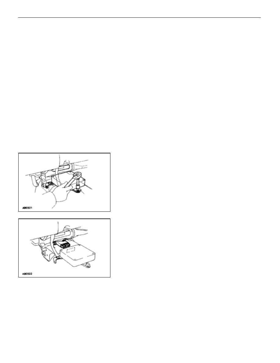
REMOVE AND INSTALL CENTER
AIRBAG SENSOR ASSEMBLY
(a) Using a torx wrench, loosen and tighten the three
screws.
Torx wrench: T40 (Part No. 09042–00020 or locally manufac-
tured tool)
Torque: 13 N
⋅
m (130 kgf
⋅
cm, 9 ft
⋅
lbf)
NOTICE:
•
Make sure the sensor assembly is installed to the speci-
fied torque.
•
If the sensor assembly has been dropped, or there are
cracks, dents or other defects in the case, bracket or
connector, replace the sensor assembly with a new one.
•
When installing the sensor assembly, take care that the
airbag wiring does not interfere with other parts and is
not pinched between other parts.
•
After installation, shake the sensor assembly to check
that there is no looseness.
(b) Disconnect the connector.
AB–19
SRS
AIRBAG – Removal and Installation of Component Parts

REPLACEMENT OF REPAIR WIRE
FOR FRONT AIRBAG SENSOR
Repair wire with two pressure–contact sleeves (Part No.
82988–50010) has been prepared for exclusive use in repairing
connector damage etc. caused by frontal collision of the vehicle.
When repairing the front airbag sensor connector on the wire har-
ness side, always use the special repair wire.
NOTICE: Do not replace the connector housing or terminal
only.
REPLACEMENT OF AIRBAG REPAIR
WIRE
CAUTION: Work must be started after approx. 20
seconds or longer from the time the ignition switch is
turned to the “LOCK” position and the negative (–) termi-
nal cable is disconnected from the battery.
1.
DISCONNECT WIRE HARNESS AT VEHICLE SIDE
(a) Remove the cover at the rear of the connector housing
and expose the wire harness.
(b) Cut the wire harness behind the connector housing.
HINT: The operation is performed more easily if the wire har-
ness is left as long as possible.
2. CONNECT
FRONT AIRBAG SENSOR WIRE HARNESS AT
VEHICLE SIDE AND REPAIR WIRE
(a) Start
stripping at least 8 mm (0.31 in.) to 11 mm (0.43 in.)
away from the end of the existing harness at vehicle side
and also from the end of the repair wire.
NOTICE: Take care not to damage the wire when strip-
ping the wire harness lead. After finishing the operation,
visually inspect the wire. If there is any damage, perform
the operation again.
(b) Overlap the two stripped wire ends inside of the
pressure–contact sleeve as illustrated in the left.
HINT: The blue pressure–contact sleeve (Part No.
AB–20
SRS
AIRBAG – Replacement of Repair Wire for Front Airbag Sensor

HINT: You might find it easier if you use a miniature screwdriv-
er as a guide as you insert wires into the sleeve.
(c) The crimping tool (AMP Part No. 169060) has color
marks on it. Place the sleeve in the correct section of the
tool according to the color of the sleeve itself.
HINT: As the crimping tool, AMP “Part No. 169060” is conve-
nient to use.
(d) With the center of the sleeve correctly placed between
the crimping jaws, squeeze the crimping tool until either
end comes into contact at the section marked by
“CLOSE HERE”.
HINT: Check to see that the sleeve and wires are still in
the correct position before closing the crimping tool
ends with steady pressure.
(e) Pull the joined wires to either end. Make sure that they
are jointed firmly by the sleeve.
NOTICE: If the jointed wires come loose the splice is de-
fective, so replace the sleeve and repeat the procedure.
(f)
Crimp both ends of the sleeve with the crimping tool at
the “INS” position.
AB–21
SRS
AIRBAG – Replacement of Repair Wire for Front Airbag Sensor
3.
PROTECT JOINED SECTION
Wrap silicon tape around the joins to protect them from water.
HINT:
•
Before starting the operation, thoroughly wipe dirt and
grease off the sections to be joined.
•
If the adhesive surfaces of two tapes come in contact
they will stick together and will not come apart, so do not
remove the backing film except when using the tape.
•
Do not let oil and dust, etc. get on the tape surface.
(a) Ready about 100 mm (3.94 in.) of silicon tape (Part No.
08231–00045) and peel off the film.
(b) Stretch the silicon tape until its width is reduced by half.
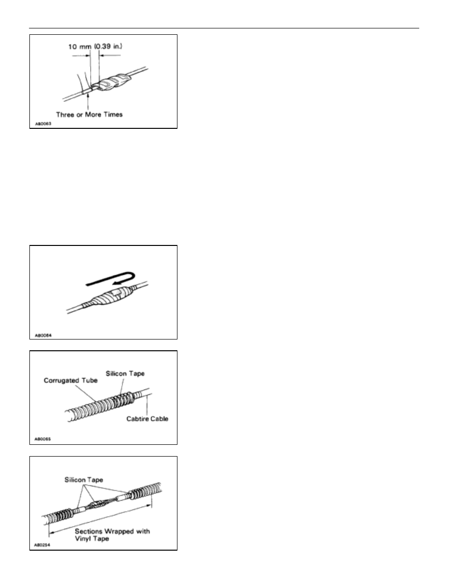
(c) About 10 mm (0.39 in.) from the end of the
pressure–contact sleeve, wrap the silicon tape around
the sleeve three or more times while stretching the tape.
(d) Wrap the remaining part of sleeve with half of the tape
overlapping at each turn.
(e) Firmly wrap the tape two times or more about 10 mm
(0.39 in.) from the other end of the pressure–contact
sleeve, then wrap the tape back towards the start again
and firmly finish winding the tape around the center of
the sleeve.
(f)
Fix the corrugated tube to the cabtire cable using silicon
tape.
(g) After applying the silicon tape, apply vinyl tape on the
corrugated tube of repair wire side over to the
corrugated tube of vehicle wire harness side.
AB–22
SRS
AIRBAG – Replacement of Repair Wire for Front Airbag Sensor
Нет комментариевНе стесняйтесь поделиться с нами вашим ценным мнением.
Текст