Lexus SC300 / Lexus SC400. Service manual — part 32
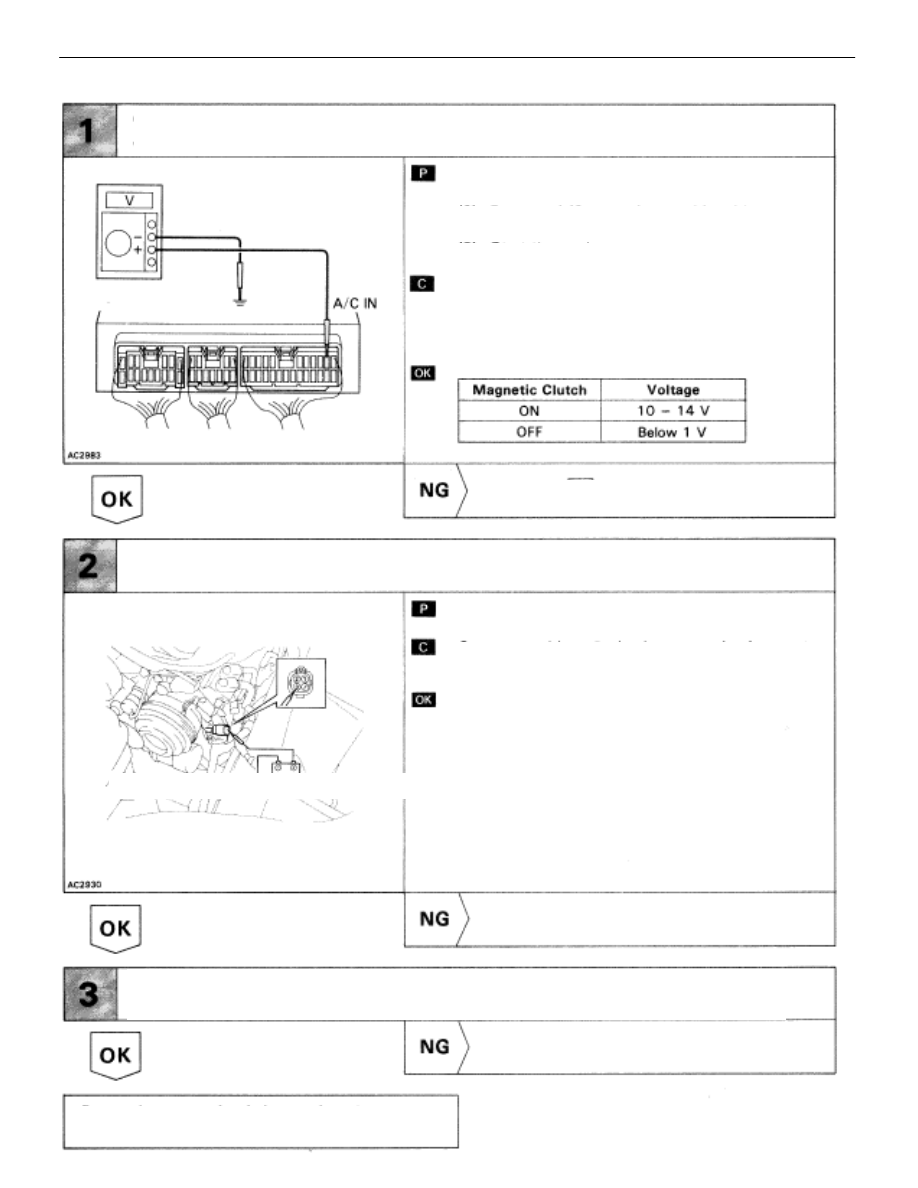
Check voltage between terminals A/C IN of air conditioner control
assembly connector and body ground.
(1)
Remove console upper panel.(See page
).
(2)
Remove A/C control assembly with
connectors still connected.
(3)
Start the engine.
Check voltage between terminals A/C IN of air condi-
tioner control assembly and body ground when mag-
netic clutch is on and off by A/C switch
Go to step (4).
Check air conditioner compressor magnetic clutch.
Disconnect magnetic clutch connector.
Connect positive
lead connected to battery to mag-
netic clutch connector terminal 3.
Magnetic clutch is energized.
Repair air conditioner compressor magnetic
clutch.
Check for open and short in harness and connecter between air
conditioner compressor and compressor relay (See page
).
Repair or replace harness or connector.
Proceed to next circuit inspection shown on ma-
trix chart (See pageAC-36).
INSPECTION PROCEDURE
AC–86
–
AIR CONDITIONING SYSTEM
Troubleshooting

Check voltage between terminals MGC of air conditioner control assem-
bly connector and body ground.
(1)
Remove console upper panel.(See page
(2)
Remove A/C control assembly with connec–
tors still connected.
(3)
Start the engine.
Check voltage between terminals MGC of air condi-
tioner control assembly connector and body ground
when magnetic clutch is on and off by A/C
switch.
Go to step (7).
Check voltage between terminals MGC of air conditioner control assem-
bly harness side connector and body ground.
(1)
Disconnect air conditioner control assembly
connector.
(3)
Turn ignition switch ON.
Check voltage between terminals MGC of air condi-
tioner control assembly harness side connector and
body ground.
Voltage:
4 – 6 V
Check and replace air conditioner control
assembly.
Check for open and short in harness and connector between
air conditioner control assembly and engine & ECT ECU (See page
Repair or replace harness or connector.
Check and replace engine & ECT ECU.
–
AIR CONDITIONING SYSTEM
Troubleshooting
AC–87

Check magnetic clutch relay.
Remove magnetic clutch relay from R/B No. 2
Check continuity between each pair of terminals
shown below of magnetic clutch relay.
(1)
Apply battery voltage between terminals 2
and 3
(2)
Check continuity between terminals 4 and 1
Replace magnetic relay.
(1)
Remove engine & ECT ECU with connectors
still connected.
(2)
Turn ignition switch ON.
(1)
Push one of the fan speed control switches
(Lo, Med or Hi).
(2)
Measure voltage between terminal ACMG of
engine & ECT ECU connector and body
ground.
Go to step (10).
Check voltage between terminal ACMG of engine & ECT ECU and
body ground.
Check for open and short in harness and connector between engine &
ECT ECU and battery (See page
Repair or replace harness or connector.
Check and replace engine & ECT ECU.
Check for open and short in harness and connector between air conditioner control
assembly and compressor relay, compressor relay and battery (See page
Repair or replace harness or connector.
Check and replace air conditioner control assembly.
AC–88
–
AIR CONDITIONING SYSTEM
Troubleshooting

ÑÑÑÑÑÑÑÑÑÑÑÑÑÑÑÑÑÑÑÑÑÑÑÑÑÑÑÑÑÑÑÑÑÑÑÑ
ÑÑÑÑÑÑÑÑÑÑÑÑÑÑÑÑÑÑÑÑÑÑÑÑÑÑÑÑÑÑÑÑÑÑÑÑ
ÑÑÑÑÑÑÑÑÑÑÑÑÑÑÑÑÑÑÑÑÑÑÑÑÑÑÑÑÑÑÑÑÑÑÑÑ
Water Valve VSV Circuit
CIRCUIT DESCRIPTION
If the target air mix damper position is on the hot side beyond a predetermined level, the A/C control
assembly turns ON Tr inside the A/C control assembly.
This turns the water valve VSV ON so that engine coolant flows to the heater core.
If the target air mix damper position is on the cool side beyond a predetermined level, the A/C control
assembly OFF Tr inside the A/C control assembly.
This turns OFF the VSV and stops circulation of engine coolant to the heater core, thus increasing the
cooling performance.
DIAGNOSTIC CHART
Check voltage between terminal WV of A/C
control assembly connector and body
ground .
Check water valve VSV.
Check for open and short in harness
and connector between VSV and A/C
control assembly .
Check and replace A/C control assembly.
Replace water valve VSV.
Repair or replace harness or
connector.
Proceed to next circuit inspection
shown on matrix chart
WIRING DIAGRAM
AC–90
–
AIR CONDITIONING SYSTEM
Troubleshooting
Нет комментариевНе стесняйтесь поделиться с нами вашим ценным мнением.
Текст