Lexus ES300 (1997 year). Service manual — part 486
IN0HC–01
N20112
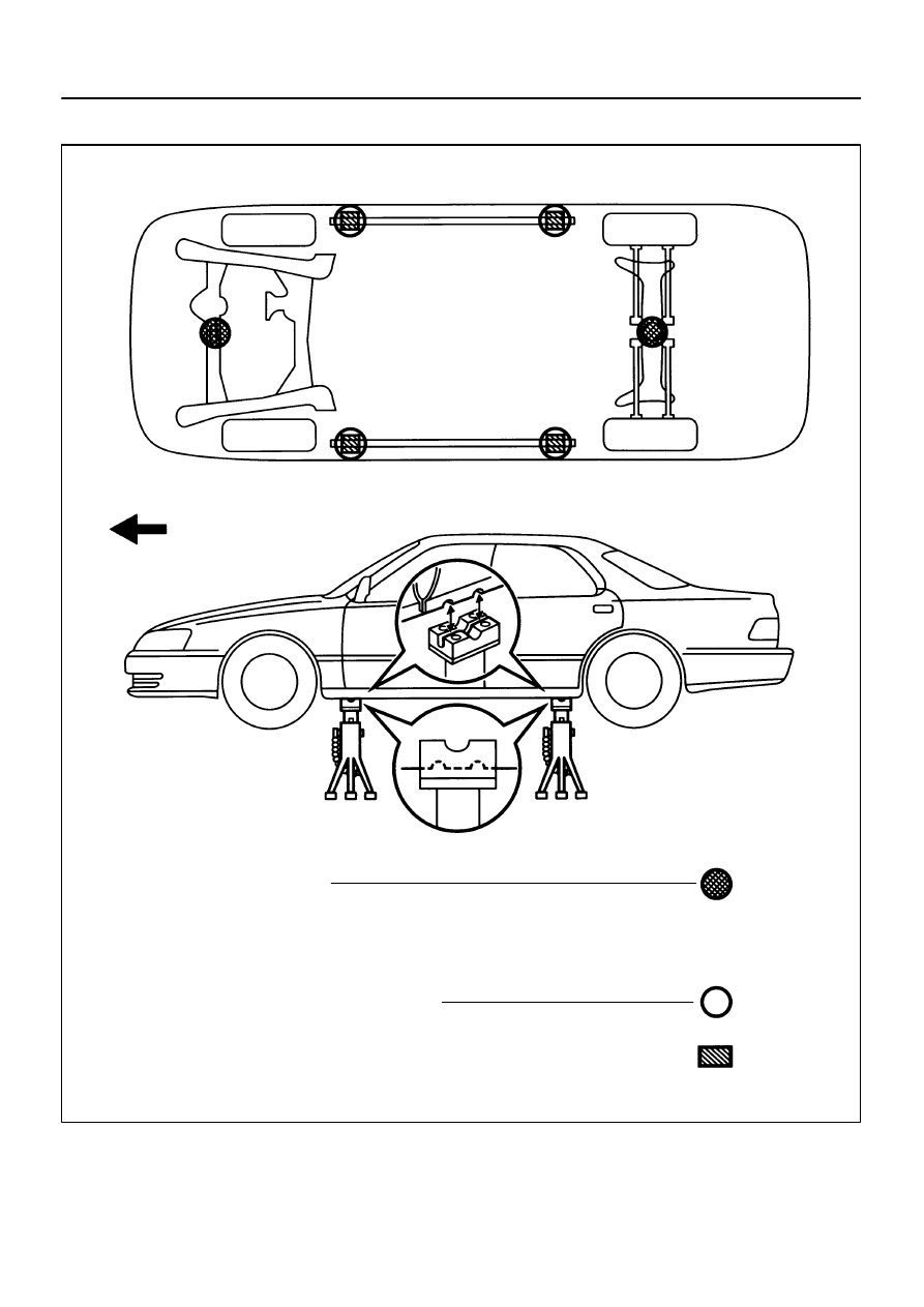
JACK POSITION
Front. . . . . . Front crossmember
Front
Rear. . . . . . Rear axle beam
PANTOGRAPH JACK POSITION
SUPPORT POSITION
Safety stand and swing arm type lift . . . . . . . . . . . ...
CAUTION: When jacking–up the front and rear, make sure the car is not
carrying any extra weight.
IN–8
–
INTRODUCTION
REPAIR INSTRUCTIONS
8
1997 LEXUS ES300 (RM511U)
VEHICLE LIFT AND SUPPORT LOCATIONS

BO4111
Negative Cable
IN0GE–01
–
INTRODUCTION
FOR ALL OF VEHICLES
IN–9
9
1997 LEXUS ES300 (RM511U)
FOR ALL OF VEHICLES
PRECAUTION
1.
FOR VEHICLES EQUIPPED WITH SRS AIRBAG AND
SEAT BELT PRETENTIONER
(a)
The LEXUS ES300 is equipped with an SRS (Supple-
mental Restraint System), such as the driver airbag, front
passenger airbag, side airbag and seat belt pretensioner.
Failure to carry out service operations in the correct se-
quence could cause the supplemental restraint system to
unexpectedly deploy during servicing, possibly leading to
a serious accident.
Further, if a mistake is made in servicing the supplemental
restraint system, it is possible the SRS may fail to operate
when required. Before servicing (including removal or
installation of parts, inspection or replacement), be sure
to read the following items carefully, then follow the cor-
rect procedure described in this manual.
(b)
GENERAL NOTICE
(1)
Malfunction symptoms of the supplemental re-
straint system are difficult to confirm, so the diag-
nostic trouble codes become the most important
source of information when troubleshooting. When
troubleshooting the supplemental restraint system,
always inspect the diagnostic trouble codes before
disconnecting the battery (See page
(2)
Work must be started after 90 seconds from the
time the ignition switch is turned to the ”LOCK” posi-
tion and the negative (–) terminal cable is discon-
nected from the battery.
(The supplemental restraint system is equipped
with a back–up power source so that if work is
started within 90 seconds of disconnecting the neg-
ative (–) terminal cable from the battery, the SRS
may deploy.)
When the negative (–) terminal cable is discon-
nected from the battery, memory of the clock and
audio systems will be cancelled. So before starting
work, make a record of the contents memorized by
the each memory system. Then when work is fin-
ished, reset the clock and audio systems as before.
To avoid erasing the memory of each memory sys-
tem, never use a back–up power supply from out-
side the vehicle.
AB0244
Matchmarks
(Red)
IN–10
–
INTRODUCTION
FOR ALL OF VEHICLES
10
1997 LEXUS ES300 (RM511U)
(3)
Even in cases of a minor collision where the SRS
does not deploy, the steering wheel pad and pas-
senger’s airbag assembly, should be inspected
(See page
).
(4)
Never use SRS parts from another vehicle. When
replacing parts, replace them with new parts.
(5)
Before repairs, remove the airbag sensor if shocks
are likely to be applied to the sensor during repairs.
(6)
Never disassemble and repair the airbag sensor as-
sembly, steering wheel pad or front passenger air-
bag in order to reuse them.
(7)
If the airbag sensor assembly, steering wheel pad
or front passenger airbag have been dropped, or if
there are cracks, dents or other defects in the case,
bracket or connector, replace them with new ones.
(8)
Do not expose the airbag sensor assembly and
steering wheel pad directly to hot air or flames.
(9)
Use a volt/ohmmeter with high impedance (10 k
Ω
/V
minimum) for troubleshooting of the electrical cir-
cuit.
(10) Information labels are attached to the periphery of
the SRS components. Follow the instructions on the
notices.
(11) After work on the supplemental restraint system is
completed, check the SRS warning light (See page
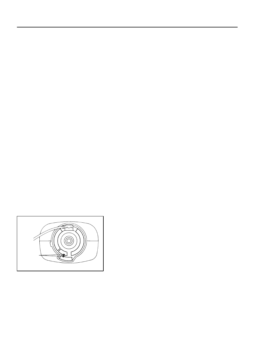
(c)
SPIRAL CABLE (in Combination Switch)
The steering wheel must be fitted correctly to the steering
column with the spiral cable at the neutral position, other-
wise cable disconnection and other troubles may result.
Refer to
of this manual concerning correct steer-
ing wheel installation.

Z13952
Correct
Wrong
Example:
Z13950
Example:
–
INTRODUCTION
FOR ALL OF VEHICLES
IN–11
11
1997 LEXUS ES300 (RM511U)
(d)
STEERING WHEEL PAD (with Airbag)
(1)
When removing the steering wheel pad or handling
a new steering wheel pad, it should be placed with
the pad top surface facing up.
In this case, the twin–lock type connector lock lever
should be in the locked state and care should be
taken to place it so the connector will not be dam-
aged. In addition do not store a steering wheel pad
on top of another one. Storing the pad with its metal-
lic surface facing upward may lead to a serious acci-
dent if the airbag inflates for some reason.
(2)
Never measure the resistance of the airbag squib.
(This may cause the airbag to deploy, which is very
dangerous.)
(3)
Grease should not be applied to the steering wheel
pad and the pad should not be cleaned with deter-
gents of any kind.
(4)
Store the steering wheel pad where the ambient
temperature remains below 93
°
C (200
°
F), without
high humidity and away from electrical noise.
(5)
When using electric welding, first disconnect the air-
bag connector (yellow color and 2 pins) under the
steering column near the combination switch con-
nector before starting work.
(6)
When disposing of a vehicle or the steering wheel
pad alone, the airbag should be deployed using an
SST before disposal (See page
).
Carry out the operation in a safe place away from
electrical noise.
Нет комментариевНе стесняйтесь поделиться с нами вашим ценным мнением.
Текст