Lexus ES300 (1997 year). Service manual — part 77
AUTOMATIC TRANSAXLE
OIL PUMP
-
AX-35
3.
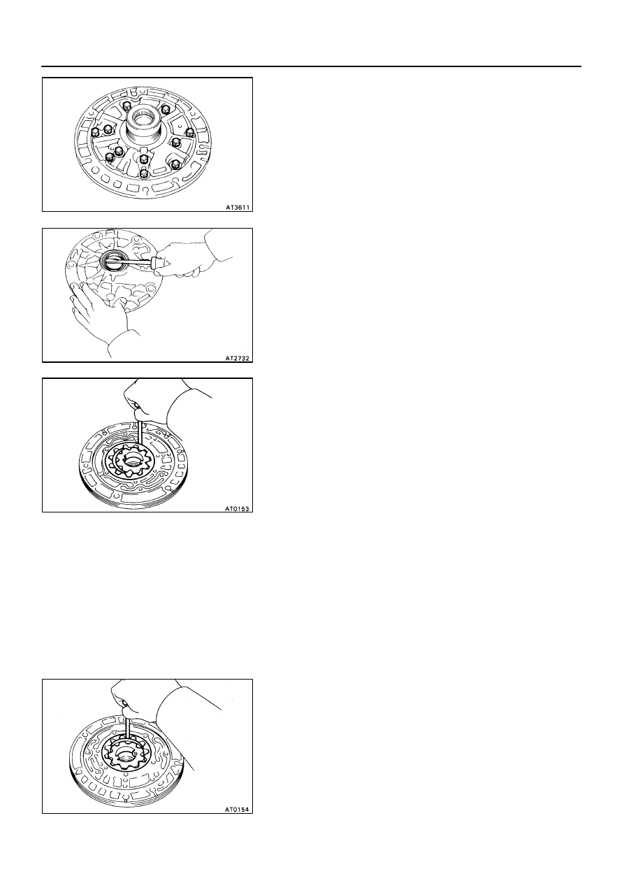
REMOVE STATOR SHAFT
Remove the 11 bolts and stator shaft.
HINT: Keep the gears in assembly order.
4.
REMOVE FRONT OIL SEAL
Pry off the oil seal with a screwdriver.
OIL PUMP BUSHING INSPECTION
1.
CHECK BODY CLEARANCE OF DRIVEN GEAR
Push the driven gear to one side of the body.
Using a feeler gauge, measure the clearance.
Standard body clearance:
0.07-0.15 mm (0.0028-0.0059 in.)
Maximum body clearance:
0.30 mm (0.0118 in.)
If the body clearance is greater than the maximum, re-
place the oil pump body subassembly.
2.
CHECK TIP CLEARANCE OF DRIVEN GEAR
Measure between the driven gear teeth and the cres-
cent-shaped part of the pump body.
Standard tip clearance:
0.11-0.14 mm (0.0043-0.0055 in.)
Maximum tip clearance:
0.30 mm (0.0118 in.)
If the tip clearance is greater than the maximum, replace
the oil pump body subassembly.
AX030-06
AUTOMATIC TRANSAXLE
OIL PUMP
-
AX-36
3.
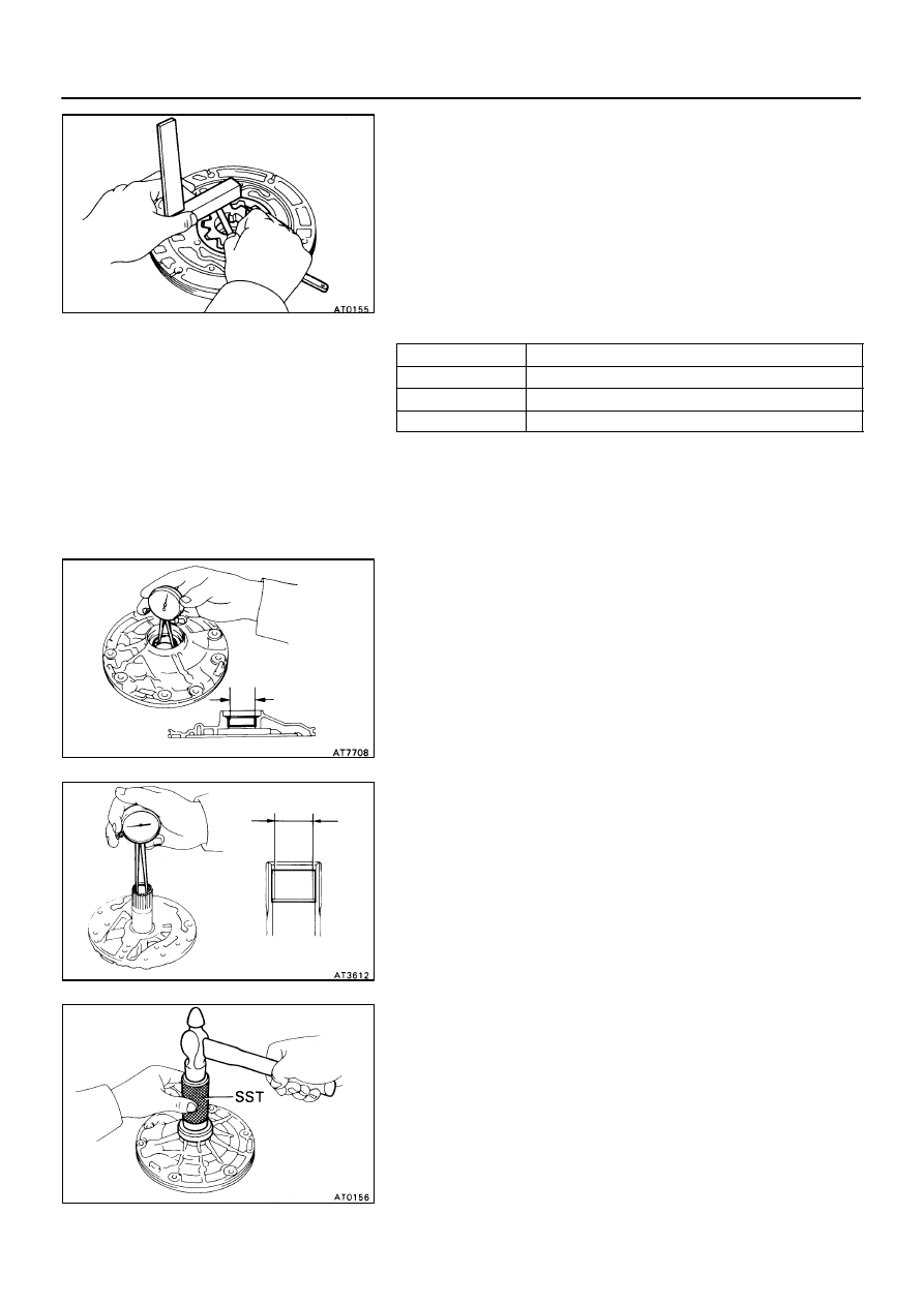
CHECK SIDE CLEARANCE OF BOTH GEARS
Using a steel straightedge and feeler gauge, measure the
side clearance of both gears.
Standard side clearance:
0.002-0.005 mm (0.0008-0.0020 in.)
Maximum side clearance:
0.100 mm (0.0039 in.)
There are 3 different thicknesses for drive and driven
gears.
Drive and driven gear thickness
Mark
Thickness mm (in.)
A
9.440-9.456 (0.3717-0.3723)
B
9.456-9.474 (0.3723-0.3730)
C
9.474-9.490 (0.3730-0.3736)
If the thickest gear can not make the side clearance within
standard specification, replace the oil pump body subas-
sembly.
4.
CHECK OIL PUMP BODY BUSHING
Using a dial indicator, measure the inside diameter of the
oil pump body bushing.
Maximum inside diameter:
38.18 mm (1.5031 in.)
If the inside diameter is greater than the maximum, re-
place the oil pump body subassembly.
5.
CHECK STATOR SHAFT BUSHING
Using a dial indicator, measure the inside diameter stator
shaft bushing.
Maximum inside diameter:
21.57 mm (0.8492 in.)
If the inside diameter is greater than the maximum, re-
place the stator shaft.
OIL PUMP ASSEMBLY
1.
INSTALL FRONT OIL SEAL
Using SST and a hammer, install a new oil seal. The seal
end should be flush with the outer edge of the pump body.
SST 09350-32014 (09351-32140)
AX031-02

AUTOMATIC TRANSAXLE
OIL PUMP
-
AX-37
2.
INSTALL DRIVEN GEAR AND DRIVE GEAR
Make sure the top of the gears are facing upward.
3.
INSTALL STATOR SHAFT TO PUMP BODY
(a)
Align the stator shaft with each bolt hole.
(b)
Torque the 11 bolts.
Torque: 10 N·m (100 kgf·cm, 7 ft·lbf)
4.
INSTALL THRUST WASHER
(a)
Coat the thrust washer with petroleum jelly.
(b)
Align the tab of the washer with the hollow of the pump
body.
5.
INSTALL OIL SEAL RINGS
Install the 2 oil seal rings to the stator shaft back side.
NOTICE: Do not spread the ring ends more than necessary.
HINT: After installing the oil seal rings, check that they
move smoothly.
6.
CHECK PUMP DRIVE GEAR ROTATION
Turn the drive gear with 2 screwdrivers and make sure it
rotates smoothly.
NOTICE: Be careful not to damage the oil seal lip.
AUTOMATIC TRANSAXLE
DIRECT CLUTCH
-
AX-38
DIRECT CLUTCH
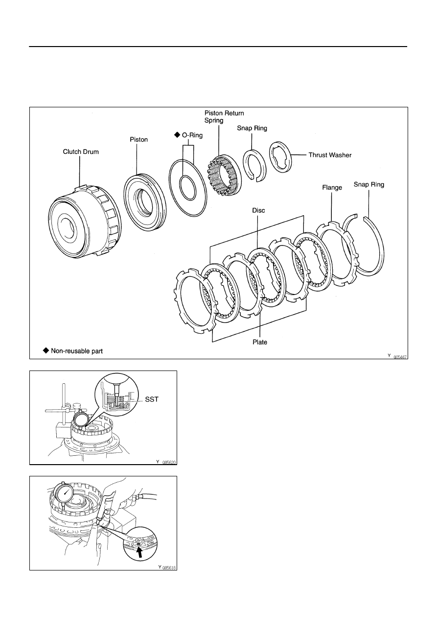
COMPONENTS
DIRECT CLUTCH DISASSEMBLY
1.
CHECK PISTON STROKE OF DIRECT CLUTCH
(a)
Install the direct clutch on the oil pump.
(b)
Install a dial indicator and measuring terminal (SST) to-
gether, measure the direct clutch piston stroke while ap-
plying and releasing compressed air (392-785 kPa, 4-8
kg/cm
2
, 57-114 psi).
SST 09350-32014 (09351-32190)
Piston stroke:
0.91-1.35 mm (0.0358-0.0531 in.)
If the piston stroke is greater than the maximum, inspect
each component.
AX032-02
AX033-05
Нет комментариевНе стесняйтесь поделиться с нами вашим ценным мнением.
Текст