Lexus ES300 (1997 year). Service manual — part 104

N20131
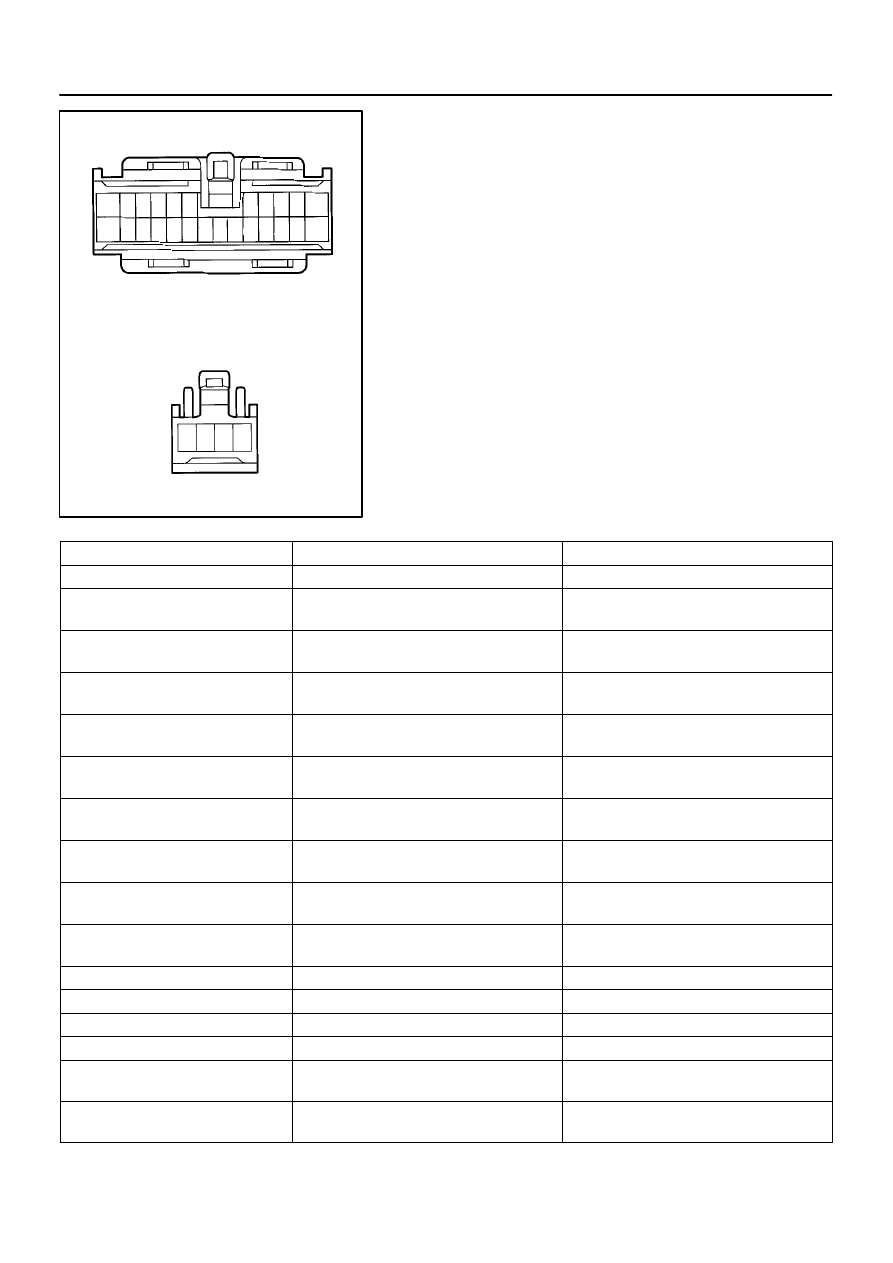
10 6 5 1
N20135
Junction Block Side
1211
1
2
3
10
9 8 7 6 5 4
BE–22
–
BODY ELECTRICAL
IGNITION SWITCH AND KEY UNLOCK WARNING
SWITCH
1406
1997 LEXUS ES300 (RM511U)
(f)
Connect the negative (–) lead from the battery to terminal
6.
(g)
Disconnect the negative (–) lead from the battery to termi-
nal 5.
(h)
Check that the buzzer stops sounding.
If operation is not as specified, replace the relay.
6.
INSPECT INTEGRATION RELAY CIRCUIT
(a)
Remove the relay from the junction block No.1 and in-
spect the connector on the junction block side.
Tester connection
Condition
Specified condition
2 – Ground
All door courtesy switches OFF (Door closed)
No continuity
2 – Ground
One of the door courtesy switches ON (Door
opened)
Continuity
4 – Ground
Door courtesy switches except that of the driver’s
door OFF (Door closed)
No continuity
4 – Ground
One of the door courtesy switches except that of
the driver’s door ON (Door opened)
Continuity
3 – Ground
Door outside handle switch OFF
No continuity
3 – Ground
Door outside handle switch ON
Continuity
5 – Ground
Key unlock warning switch OFF
No continuity
5 – Ground
Key unlock warning switch ON
Continuity
6 – Ground
Driver’s door courtesy switch OFF (Door closed)
No continuity
6 – Ground
Driver’s door courtesy switch ON (Door opened)
Continuity
8 – Ground
Buckle switch OFF (Seat belt unfastened)
No continuity
8 – Ground
Buckle switch ON (Seat belt fastened)
Continuity
10 – Ground
Constant
Continuity
1 – Ground
Constant
Battery positive voltage
7 – Ground
9 – Ground
Ignition switch LOCK or ACC
No voltage
7 – Ground
9 – Ground
Ignition switch ON
Battery positive voltage
11 – Ground
Ignition switch LOCK
No voltage
11 – Ground
Ignition switch ACC or ON
Battery positive voltage
N20137
Wire Harness Side
Wire Harness Side
Connctor ”A”
Connctor ”B”
1
4
7
10
2 3
5 6
8 9
11
12 13 14 15 16 17 18 19 20 21 22 23 24 25
1
4
2 3
eh–25–1
h–4–1
–
BODY ELECTRICAL
IGNITION SWITCH AND KEY UNLOCK WARNING
SWITCH
BE–23
1407
1997 LEXUS ES300 (RM511U)
(b)
Disconnect the connector from the integration relay and
inspect the connectors on the wire harness side.
Tester connection
Condition
Specified condition
A3 – Ground
Constant
Continuity
A5 – Ground
Driver’s door unlock detection switch OFF (Door
closed)
No continuity
A5 – Ground
Driver’s door unlock detection switch ON (Door
opened)
Continuity
A6 – Ground
Passenger’s door courtesy switch OFF (Door
closed)
No continuity
A6 – Ground
Passenger’s door courtesy switch ON (Door
opened)
Continuity
A7 – Ground
Passenger’s door unlock detection switch OFF
(Door closed)
No continuity
A7 – Ground
Passenger’s door unlock detection switch ON
(Door opened)
Continuity
A9 – Ground
Rear door unlock detection switch OFF (Door
closed)
No continuity
A9 – Ground
Rear door unlock detection switch ON (Door
opened)
Continuity
A11 – A12
A12 – A25
Constant
Continuity
A16 – Ground
Door lock manual switch OFF or UNLOCK
No continuity
A16 – Ground
Door lock manual switch LOCK
Continuity
A17 – Ground
Door lock manual switch OFF or LOCK
No continuity
A17 – Ground
Door lock manual switch UNLOCK
Continuity
A18 – Ground
Driver’s and passenger’s door key lock and
unlock switch OFF or UNLOCK
No continuity
A18 – Ground
Driver’s or passenger’s door key lock and unlock
switch LOCK
Continuity

BE–24
–
BODY ELECTRICAL
IGNITION SWITCH AND KEY UNLOCK WARNING
SWITCH
1408
1997 LEXUS ES300 (RM511U)
Tester connection
Condition
Specified condition
A19 – Ground
Driver’s door key lock and unlock switch OFF or
LOCK
No continuity
A19 – Ground
Driver’s door key lock and unlock switch
UNLOCK
Continuity
A20 – Ground
Passenger’s door key lock and unlock switch
OFF or LOCK
No continuity
A20 – Ground
Passenger’s door key lock and unlock switch
UNLOCK
Continuity
A1 – Ground
Constant
Battery positive voltage
B1 – Ground
Light control switch OFF
No voltage
B1 – Ground
Light control switch TAIL or HEAD
Battery positive voltage
B4 – Ground
Light control switch OFF or TAIL
No voltage
B4 – Ground
Light control switch HEAD
Battery positive voltage
B2 – Ground
B3 – Ground
Constant
Battery positive voltage
If the circuit is as specified, try replacing the relay with a new
one.
If the circuit is not as specified, inspect the circuits connected
to other parts.

Z19392
Headlights
Automatic Light
Control Sensor
E/G Room Junction Block
HEAD (RH) Fuse
HEAD (LH) Fuse
HEAD (RH–LH) Fuse
DOME Fuse
HEAD (LH–LO) Fuse
ECU–B Fuse
Headllight Control Relay
CANADA:
E/G Room R/B No.2
HEAD (RH–LWR) fuse
HEAD (LH–LWR) fuse
D.R.L No.2 Fuse
D.R.L No.2 Relay
D.R.L No.3 Relay
D.R.L No.4 Relay
USA
CANADA
Combination Switch
Light Control Switch
Headlight Dimmer Switch
Ignition Switch
D.R.L.(MAIN) Relay
Taillight
D.R.L.:Daytime Running Light
Door Courtesy Switch
Instrument Panel
Junction Block
GAUGE Fuse
TAIL Fuse
Taillight Control Relay
Integration Relay
BE04W–01
–
BODY ELECTRICAL
HEADLIGHT AND TAILLIGHT SYSTEM
BE–25
1409
1997 LEXUS ES300 (RM511U)
HEADLIGHT AND TAILLIGHT SYSTEM
LOCATION
Нет комментариевНе стесняйтесь поделиться с нами вашим ценным мнением.
Текст