Lexus ES300 (1997 year). Service manual — part 275
BE062–01
Z19355
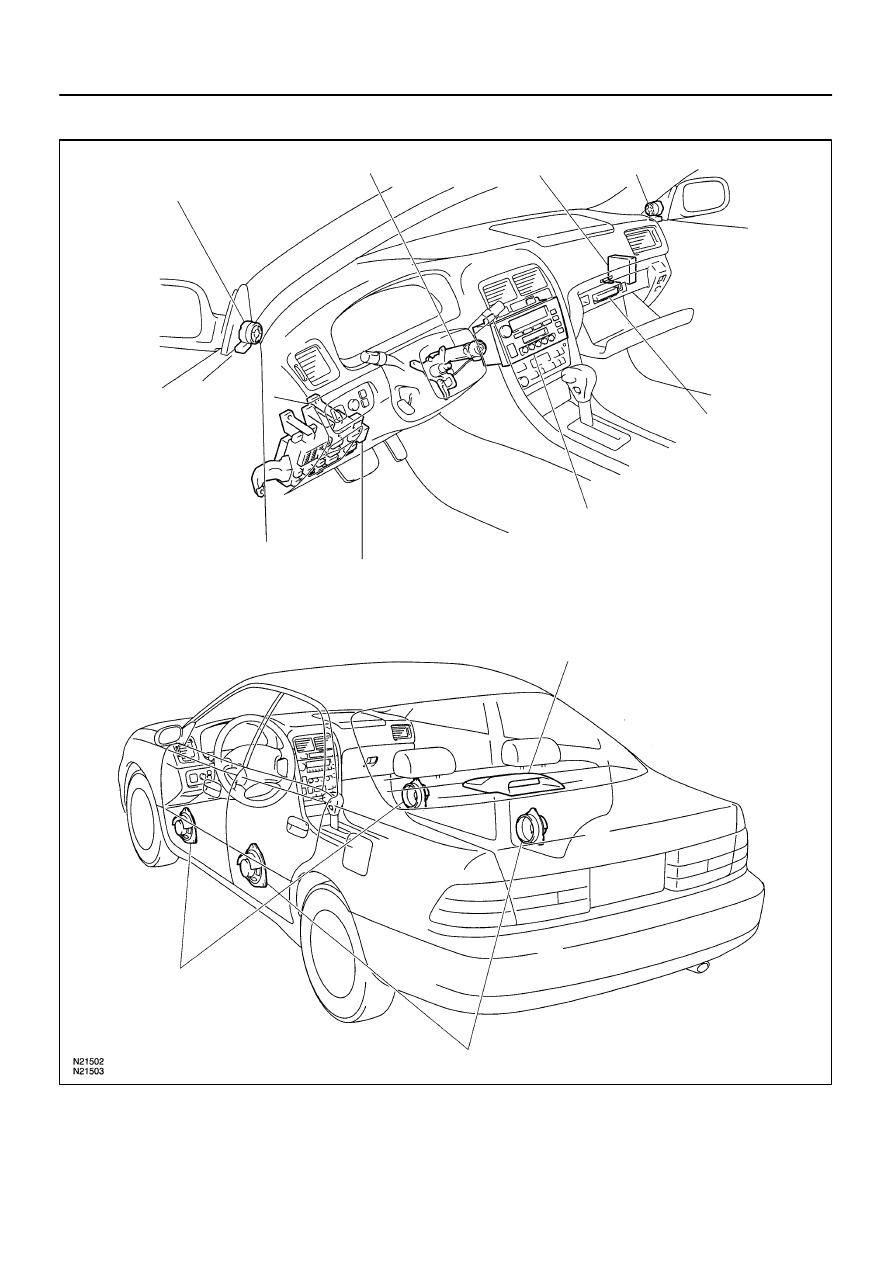
Tweeter
Ignition Switch
Power Amplifier
Tweeter
Instrument Panel Junction Block
RADIO No.1 Fuse
RAD No.2 Fuse
Radio Receiver Assembly
Woofer
CD Auto Changer
Front Speaker
Rear Speaker
BE–164
–
BODY ELECTRICAL
AUDIO SYSTEM
1548
1997 LEXUS ES300 (RM511U)
LOCATION
BE063–01
N21369
Wire Harness Side
N21370
Wire Harness Side
Connector ”A”
Connector ”B”
Connector ”C”
–
BODY ELECTRICAL
AUDIO SYSTEM
BE–165
1549
1997 LEXUS ES300 (RM511U)
INSPECTION
1.
INSPECT CD AUTO CHANGER CIRCUIT
Disconnect connectors from CD auto changer and inspect the
connector on the wire harness side.
Tester connection
Condition
Specified condition
8 – Ground
Constant
Continuity
5 – Ground
Constant
Battery positive voltage
12 – Ground
Ignition switch LOCK
No voltage
12 – Ground
Ignition switch ACC or ON
Battery positive voltage
If the circuit is not as specified, inspect the circuits connected
to other parts.
HINT:
Check the wire harness between the radio receiver as-
sembly and the CD auto changer.
Since the signals to and from the MUTE, R
–
, R
+
, L
–
, L
+
,
TX
–
and TX
+
terminals are serial signals, they cannot or-
dinarily be measured with a tester.
2.
INSPECT POWER AMPLIFIER CIRCUIT
Disconnect the connector from power amplifier and inspect the
connector on the wire harness side.
Tester connection
Condition
Specified condition
C7 – Ground
Constant
Continuity
C3 – Ground
Ignition switch LOCK
No voltage
C3 – Ground
Ignition switch ACC or ON
Battery positive voltage
C4 – Ground
Constant
Battery positive voltage
If the circuit is not as specified, inspect the circuits connected
to other parts.

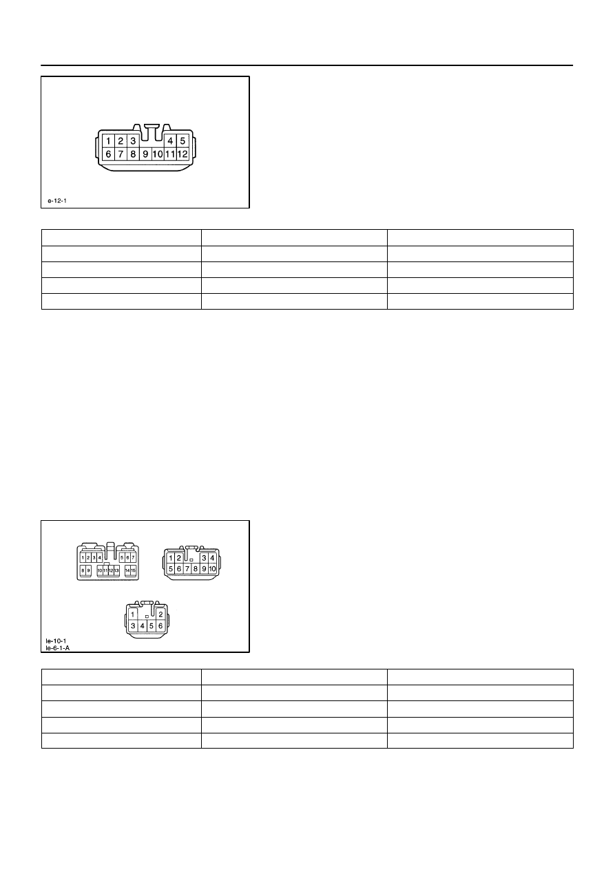
Z05935
Wire Harness Side
Connector ”A”
Connector ”B”
BE6542 e–12–1
BE–166
–
BODY ELECTRICAL
AUDIO SYSTEM
1550
1997 LEXUS ES300 (RM511U)
3.
INSPECT RADIO RECEIVER ASSEMBLY CIRCUIT
Disconnect the connectors from the radio receiver assembly,
and inspect the connector on the wire harness side.
Tester connection
Condition
Specified condition
A4 – Ground
Constant
Battery positive voltage
A3 – Ground
Ignition switch LOCK
No voltage
A3 – Ground
Ignition switch ACC or ON
Battery positive voltage
If the circuit is not as specified, inspect the circuits connected
to other parts.
HINT:
Check the wire harness between radio receiver assembly and
the CD auto changer, between radio receiver assembly and
power amplifier.
4.
INSPECT GLASS IN PRINTED ANTENNA
(Use same procedure as for ”INSPECT DEFOGGER WIRES”
on page BE–126.)
5.
REPAIR GLASS PRINTED ANTENNA
(Use same procedure as for ”REPAIR DEFOGGER WIRES” on
page BE–127.)
N21504
BE064–01
–
BODY ELECTRICAL
ANTENNA CORD
BE–167
1551
1997 LEXUS ES300 (RM511U)
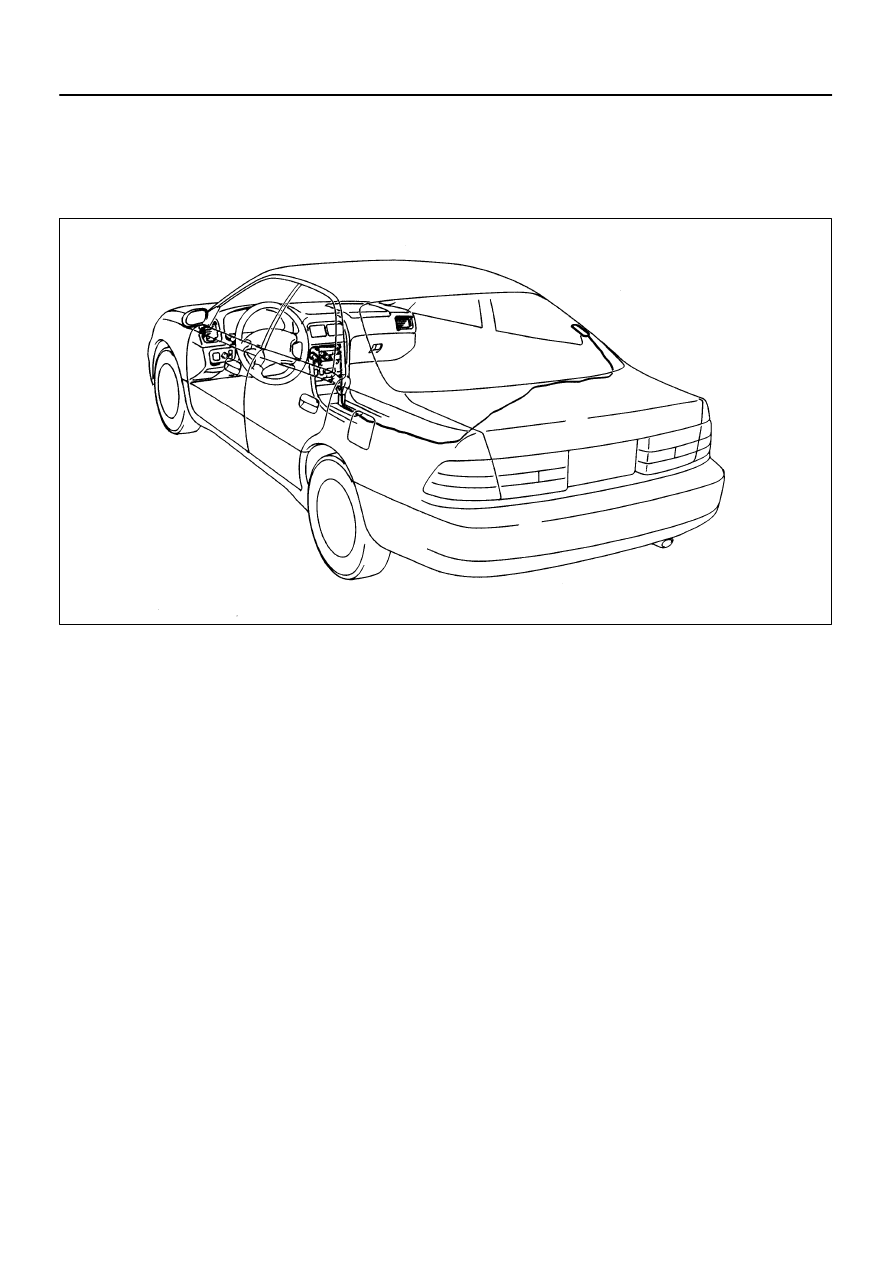
ANTENNA CORD
REMOVAL
REMOVE ANTENNA CORD
(a)
Remove the following parts:
Instrument panel assembly
Console box
Rear seat
Right rear poller garnish
Package tray trim
Room partition trim
HINT:
See BO section
(b)
Remove antenna cord from glass printed antenna.
(c)
Disconnect the connectors shown in the illustration.
(d)
Remove the clips and antenna cord assembly.
Нет комментариевНе стесняйтесь поделиться с нами вашим ценным мнением.
Текст