Lexus ES300 (1997 year). Service manual — part 411
N22066
Theft Deterrent ECU
ACC
13
12
IG
P–L
A
A
J/C
J7
P–L
B–R
B
C
B–R
Instrument Panel J/B
1
6
8
1
1
2
3
L–R
4
B–Y
AM1
2
Ignition Switch
W
B–R
B–R
1
FL BLOCK
1
B–G
FL MAIN
3.0W
Battery
J/C
F6
100A ALT
F11
1K
1K
1K
1T
1B
1D
40A AM1
15A ECU–IG
15A CIG
T4
T4
J6
J5
ACC
IG1
–
DIAGNOSTICS
THEFT DETERRENT SYSTEM
DI–421
573
1997 LEXUS ES300 (RM511U)
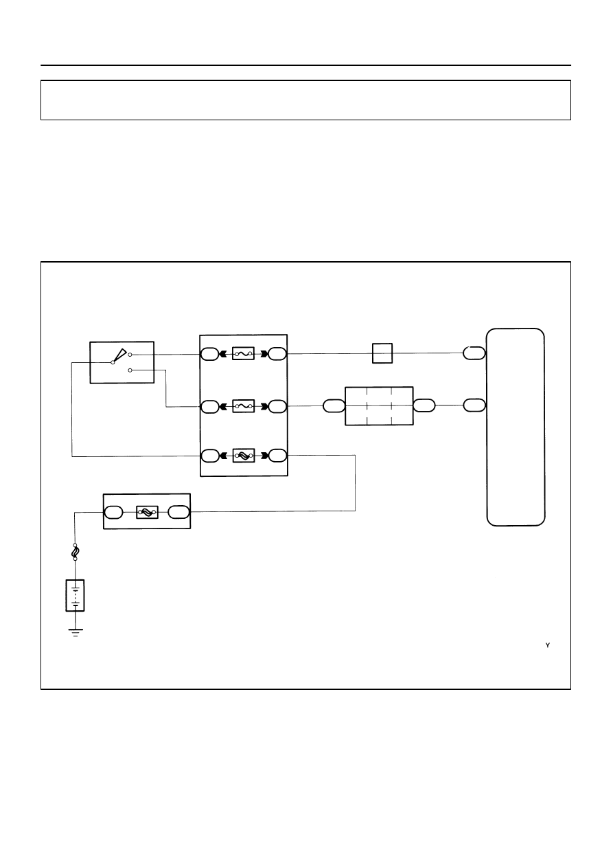
Ignition Switch Circuit
CIRCUIT DESCRIPTION
When the ignition switch is turned to the ACC position, battery positive voltage is applied to the terminal ACC
of the ECU. Also, if the ignition switch is turned to the ON position, battery positive voltage is applied to the
terminals ACC and IG of the ECU. When the battery positive voltage is applied to the terminal ACC of the
ECU while the theft deterrent system is activated, the warning stops. Furthermore, power supplied from the
terminals ACC and IG of the ECU is used as power for the door courtesy switch, and position switch, etc.
WIRING DIAGRAM
DI022–01
N20675
Instrument Panel J/B
ECU–IG Fuse
CIG Fuse
AB0119
N20681
I01283
ON
ACC
IG
(+)
(–)
DI–422
–
DIAGNOSTICS
THEFT DETERRENT SYSTEM
574
1997 LEXUS ES300 (RM511U)
INSPECTION PROCEDURE
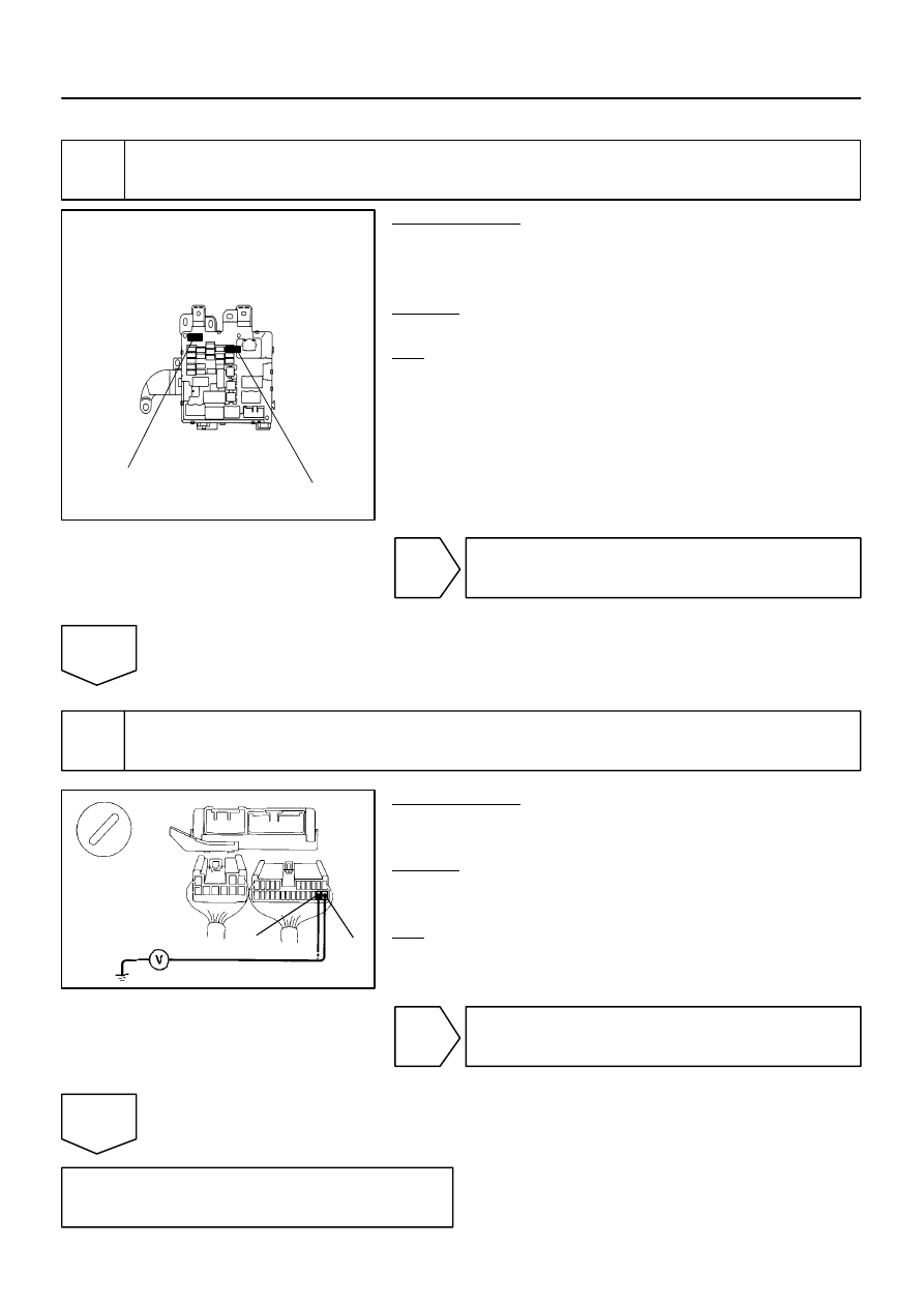
1
Check CIG and ECU–IG fuses.
PREPARATION:
(a)
Remove the fuse box opening cover.
(b)
Remove CIG and ECU–IG fuses from instrument panel
junction block.
CHECK:
Check continuity of CIG and ECU–IG fuses.
OK:
Continuity
NG
Check for short in all the harness and compo-
nents connected to the CIG and ECU–IG fuses
(See attached wiring diagram).
OK
2
Check voltage between terminals IG and ACC of theft deterrent ECU and body
ground.
PREPARATION:
(a)
Disconnect the theft deterrent ECU connectors.
(b)
Turn ignition switch ON.
CHECK:
Measure voltage between terminals IG and ACC of theft deter-
rent ECU connector and body ground.
OK:
Voltage: 10
∼
14V
NG
Check and repair harness and connector be-
tween theft deterrent ECU and battery
(See page
).
OK
Check and replace theft deterrent ECU.
N22067
1D
II
L–B
W–B
J/C
T4
Instrument Panel J/B
Theft Deterrent ECU
KSW
J10
Key Unlock
Warning Switch
1M
Instrument Panel J/B
2
1
5
3
7
7
A
1M
1D
B
B
L–B
L–B
15
W–B
SR4924
N14675
I00634
2 (–)
1 (+)
–
DIAGNOSTICS
THEFT DETERRENT SYSTEM
DI–423
575
1997 LEXUS ES300 (RM511U)
Key Unlock Warning Switch Circuit
CIRCUIT DESCRIPTION
The key unlock warning switch goes on when the ignition key is inserted in the key cylinder and goes off when
the ignition key is removed.
The ECU operates the key confinement prevention function while the key unlock warning switch is on.
WIRING DIAGRAM
INSPECTION PROCEDURE
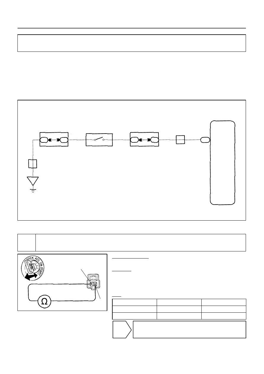
1
Check key unlock warning switch.
PREPARATION:
Disconnect key unlock warning switch connector.
CHECK:
Check continuity between terminal 1 and 2 of key unlock warn-
ing switch connector, when the key is inserted to the key cylin-
der or removed.
OK:
Switch position
Tester connection
Specified condition
ON (Key inserted)
1 – 2
Continuity
OFF (Key removed)
–
No continuity
NG
Replace key unlock warning switch.
DI023–01

DI–424
–
DIAGNOSTICS
THEFT DETERRENT SYSTEM
576
1997 LEXUS ES300 (RM511U)
OK
2
Check harness and connectors between ECU and key unlock warning switch,
key unlock warning switch and body ground (See page
NG
Repair or replace harness or connector.
OK
Check and replace theft deterrent ECU.*1
*1: When there is a malfunction that the theft deterrent system
cannot be set, proceed to the next numbered circuit inspection
shown on matrix chart (See page
Нет комментариевНе стесняйтесь поделиться с нами вашим ценным мнением.
Текст