Volvo S60 Cross Country (2018 year). Manual — part 21
MAINTENANCE AND SERVICE
360
Lamp replacement - general
Several of the car's bulbs can be replaced by
the driver. For replacement of LED lamps and
xenon lamps, please contact a workshop.
The bulbs are specified (p. 367). The following
list contains locations of bulbs and other light
sources that are specialised, such as LED
6
lamps, or are unsuitable for changing for some
other reason, except at a workshop
7
:
•
active xenon headlamps - ABL (xenon lamps)
•
daytime running lights/position lamps, front
•
cornering lights
•
side direction indicators, door mirrors
•
approach lighting, door mirrors
•
interior lighting apart from Courtesy lighting
front
•
position lamps, rear
•
side marker lamps.
WARNING
On cars with xenon headlamps, the replace-
ment of xenon lamps must be carried out at a
workshop - an authorised Volvo workshop is
recommended. Working with xenon lamps
demands extreme caution because the head-
lamp is equipped with a high voltage unit.
WARNING
The car's electrical system must be in key
position 0 for bulb replacement; see Key posi-
tions - functions at different levels (p. 77).
Never touch the glass part of the bulbs with
your fingers. Grease from your fingers is
vaporised by the heat, coating the reflector
and then causing damage.
If an error message remains after the broken
bulb has been replaced then we recommend
visiting an authorised Volvo workshop.
Outside lighting such as headlamps and rear
lamps may temporarily have condensation on
the inside of the lens. This is normal, all exte-
rior lighting is designed to withstand this.
Condensation is normally vented out of the
lamp housing when the lamp has been
switched on for a time.
Related information
•
Lamp replacement - headlamps (p. 361)
•
Lamp replacement - location of rear lamps
(p. 365)
•
Lamp replacement - vanity mirror lighting
(p. 366)
•
Lamp replacement - lighting in cargo area
(p. 366)
•
Lamp replacement - number plate lighting
(p. 366)
6
LED (Light Emitting Diode)
7
An authorised Volvo workshop is recommended.
MAINTENANCE AND SERVICE
361
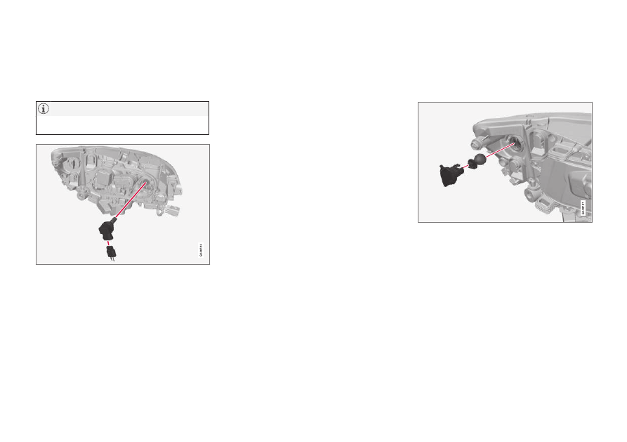
Lamp replacement - headlamps
All of the headlamp bulbs are replaced via the
engine compartment. First loosen and remove
the whole headlamp.
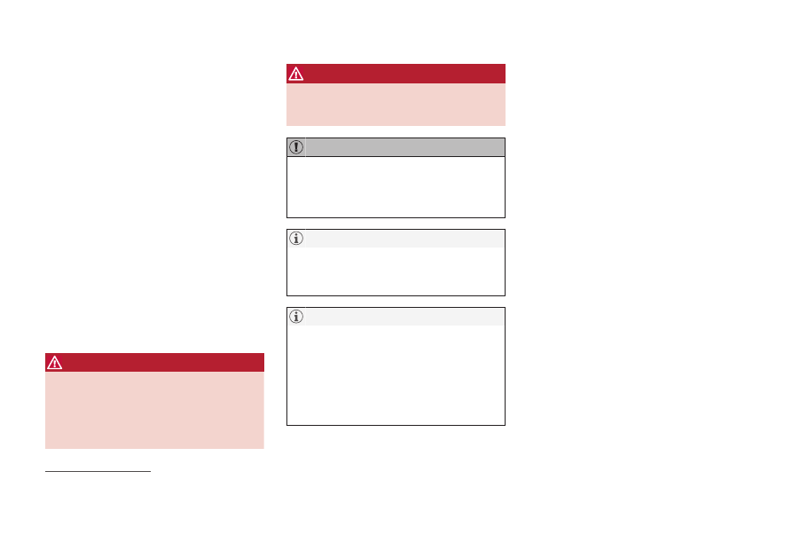
Removing the headlamp
Set the car's electrical system in key position 0,
see Key positions - functions at different levels
(p. 77).
Pull out the headlamp's locking pins.
Release the headlamp by alternately tilting
and pulling it out.
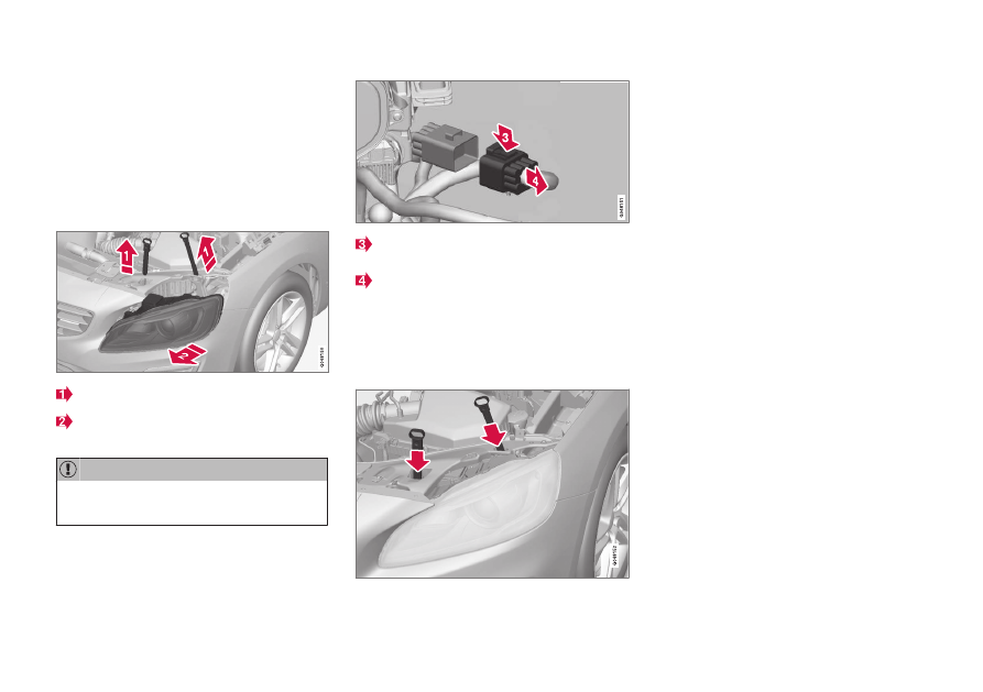
Do not pull the electrical cable, only the con-
nector.
Detach the headlamp connector by pressing
down the clip with your thumb.
At the same time, guide out the connector
with your other hand.
5. Lift out the headlamp and place it on a soft
surface to avoid scratching the lens.
6. Replace the bulb in question.
Securing the headlamp
1. Plug in the connector, a clicking sound
should be heard.
2. Reinstall the headlamp and locking pins. The
short pin is fitted closest to the radiator grille.
Check that they are firmly inserted.
3. Check the lighting.
The connector must be plugged in properly and
the headlamp mounted before the lighting is
switched on or the remote control key is inserted
in the ignition switch.
Related information
•
Lamp replacement - general (p. 360)
•
Lamp replacement - cover for main/dipped
beam bulbs (p. 362)
•
MAINTENANCE AND SERVICE
362
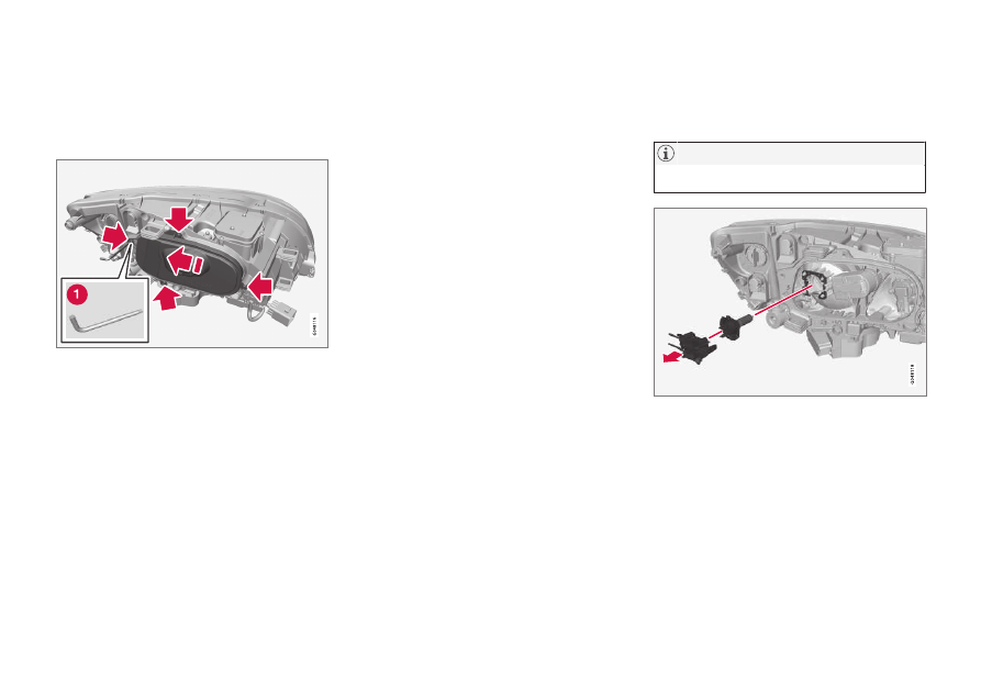
Lamp replacement - cover for main/
dipped beam bulbs
Main/dipped beam bulbs are accessed by
releasing the headlamp's larger cover.
Before starting to replace a bulb, see Lamp
replacement - headlamps (p. 361).
1. Unscrew the cover's four screws using a Torx
tool, size T20 (1). They should not be loos-
ened completely. (3 - 4 turns are sufficient.)
2. Slide the cover to one side.
3. Remove the cover.
Reinstall the cover in reverse order.
Related information
•
Lamp replacement - headlamps (p. 361)
•
Lamp replacement - dipped beam (p. 362)
•
Lamp replacement - main beam (p. 363)
•
Lamp replacement - extra main beam
(p. 364)
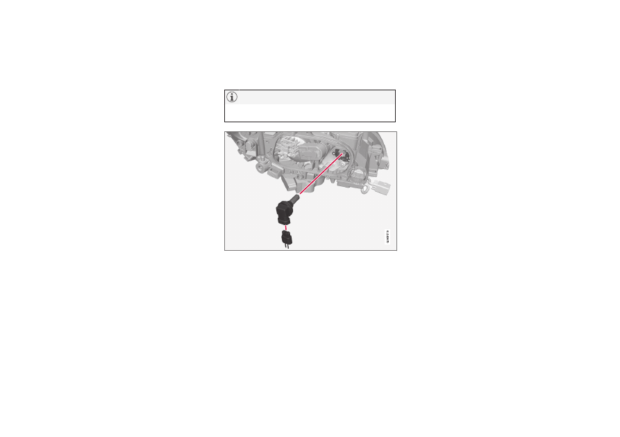
Lamp replacement - dipped beam
The dipped beam bulb is fitted inside the head-
lamp's larger cover.
Applies to cars with halogen headlamps.
1. Detach the headlamp (p. 361).
3. Unplug the connector from the bulb.
4. Detach the bulb by pulling it straight out.
5. The guide pin on the lamp should be straight
up when it is fitted and a clicking sound
should be heard when it clicks into place.
Reinstall the parts in reverse order.
MAINTENANCE AND SERVICE
363
Related information
•
Lamps - specifications (p. 367)
Lamp replacement - main beam
The main beam bulb is fitted inside the head-
lamp's larger cover.
Applies to cars with halogen headlamps.
1. Detach the headlamp (p. 361).
3. Detach the bulb by turning anticlockwise and
then pulling straight out.
4. Unplug the connector from the bulb.
5. Replace the bulb and align it in the socket
and turn clockwise in order to secure it. It
can only be secured in one position.
Reinstall the parts in reverse order.
Related information
•
MAINTENANCE AND SERVICE
* Option/accessory.
364
Lamp replacement - extra main
beam
The extra main beam bulb is fitted inside the
headlamp's larger cover.
Applies to cars with Xenon headlamps
*.
1. Detach the headlamp (p. 361).
3. Detach the bulb by turning anticlockwise and
then pulling straight out.
4. Unplug the connector from the bulb.
5. Replace the bulb and align it in the socket
and turn clockwise in order to secure it. It
can only be secured in one position.
Reinstall the parts in reverse order.
Related information
•
Lamps - specifications (p. 367)
Lamp replacement - direction
indicators front
The direction indicator lamp is fitted inside the
headlamp's smaller cover.
1. Detach the headlamp (p. 361).
2. Detach the cover by pulling it straight out.
3. Pull the bulb holder in order to extract the
bulb.
4. Press and simultaneously turn the bulb anti-
clockwise in order to detach it.
Reinstall the parts in reverse order.
Related information
•
MAINTENANCE AND SERVICE
365
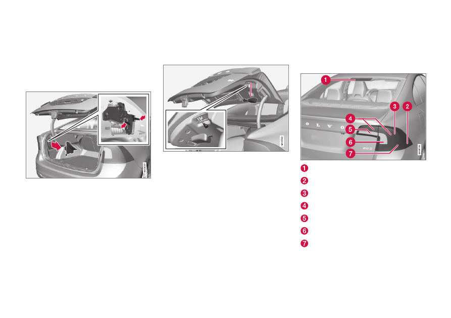
Lamp replacement - rear lamp
Lamps in the rear lamp cluster are replaced from
inside the cargo area.
The bulb for the reversing lamp is located
behind the panel in the boot lid.
Lamp housing, rear
The bulbs in the rear light cluster are replaced
from inside the cargo area (not the LED lamps).
1. Remove the covers in the left/right-hand
panel to access the bulbs. The bulbs are
located in a bulb holder.
2. Press the catches together and pull out the
bulb holder.
3. Remove the blown bulb by pressing it in and
turning anticlockwise.
4. Fit a new bulb, press down and turn clock-
wise.
5. Press the bulb holder into place and refit the
cover.
Reversing lamp
1. Open the panel in the boot lid.
2. Detach the bulb holder by turning it anti-
clockwise.
3. Remove the blown bulb by pressing it in and
turning anticlockwise.
4. Fit a new bulb, press down and turn clock-
wise.
5. Attach the bulb holder by turning it clock-
wise.
Related information
•
Lamp replacement - location of rear lamps
(p. 365)
•
Lamps - specifications (p. 367)
Lamp replacement - location of rear
lamps
The overview shows the location of the lamps at
the rear.
Brake light (LED)
Side marker lamps (LED)
Position lamps (LED)
Related information
•
Lamp replacement - general (p. 360)
•
MAINTENANCE AND SERVICE
366
Lamp replacement - number plate
lighting
The number plate lighting is located under the
boot lid handle.
1. Remove the screws with a screwdriver.
2. Carefully detach the whole bulb housing and
withdraw it.
3. Replace the bulb.
4. Refit the whole bulb housing and screw it
into place.
Related information
•
Lamps - specifications (p. 367)
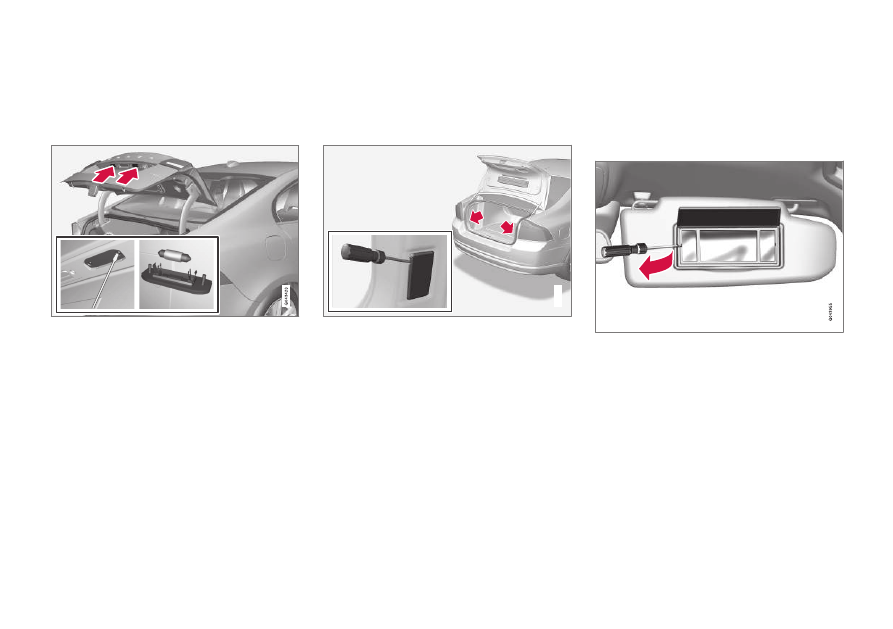
Lamp replacement - lighting in
cargo area
The cargo area lighting is positioned on both
sides of the boot lid opening.
G021758
1. Insert a screwdriver and gently prize so that
the lamp housing comes loose.
2. Replace the bulb.
3. Check that the bulb illuminates and press
back the lamp housing.
Related information
•
Lamps - specifications (p. 367)
Lamp replacement - vanity mirror
lighting
The vanity mirror's lamps are fitted inside the
lamp lenses.
Removal of lamp lens
1. Insert a screwdriver under the lamp lens and
gently prize up the lug on the edge.
2. Carefully detach and lift aside the lamp lens.
3. Use needle-nose pliers to pull the bulb
straight out to the side and replace with a
new one. Note! - Do not squeeze the bulb
too hard with the pliers. Otherwise, the bulb
glass could then break.
Attaching the lamp lens
1. Refit the lamp lens.
2. Press it into place.
MAINTENANCE AND SERVICE
367
Related information
•
Lamps - specifications (p. 367)
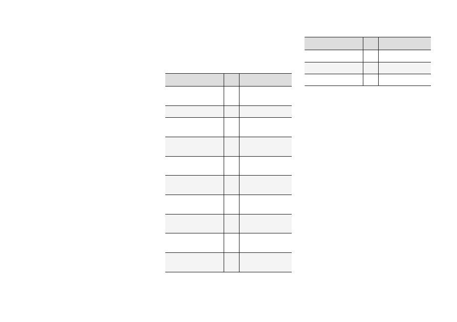
Lamps - specifications
The specifications apply to bulbs. For replace-
ment of LED lamps and xenon lamps, please
contact a workshop.
Lighting
W
A
Type
Dipped beam, halo-
gen
55
H7 LL
Main beam, halogen
65
H9
Extra main beam,
ABL
65
H9
Front direction indi-
cators
24
PY24W
Courtesy lighting
front
3
T10 Socket
W2.1x9.5d
Glovebox lighting
5
Socket SV8.5
Length 43 mm
Vanity mirror light-
ing
1.2
T5 Socket
W2x4.6d
Cargo area lighting
10
Socket SV8.5
Length 38 mm
Number plate light-
ing
5
C5W LL
Direction indicators,
rear
21
PY21W LL
Lighting
W
A
Type
Brake light
21
P21W LL
Reversing lamp
21
H21W LL
Rear fog lamp
21
H21W LL
A
Watt
Related information
•
MAINTENANCE AND SERVICE
368
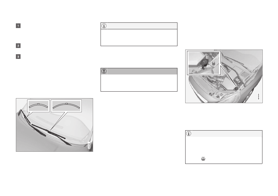
Wiper blades
The windscreen wiper blades must be in service
position when they are to be replaced.
Service position
Wiper blades in service position.
In order to change, clean or lift the wiper blades
(for scraping off ice from the windscreen, for
example) they must be in service position.
Before placing the wiper blades in the service
position, make sure that they are not frozen
down.
1. Insert the remote control key in the ignition
switch
8
and briefly press the START/STOP
ENGINE button to set the car's electrical
system to key position I. For detailed infor-
mation on key positions, see Key positions -
functions at different levels (p. 77).
2. Briefly press the START/STOP ENGINE
button again to set the car’s electrical system
in key position 0.
3. Within 3 seconds, move the right stalk switch
up and hold it in position for
approx. 1 second.
> The wipers then move to standing straight
up.
The wipers return to their starting position when
you briefly press the START/STOP ENGINE
button to set the car’s electrical system to key
position I (or when the car is started).
If the wiper arms in service position have
been folded up from the windscreen, they
must be folded back down onto the wind-
screen before the wipers are activated. This is
to avoid scraping the paint on the bonnet.
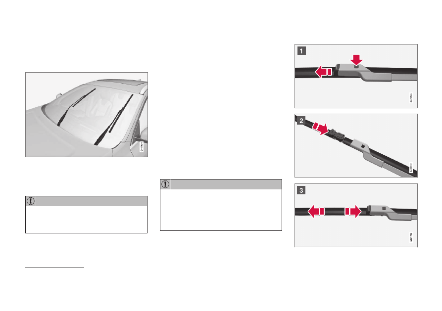
Replacing the wiper blades
8
Not required in cars with keyless start and lock system.
MAINTENANCE AND SERVICE
}}
369
Fold up the wiper arm when it is in service
position. Press the button located on the
wiper blade mounting and pull straight out
parallel with the wiper arm.
Slide in the new wiper blade until a "click" is
heard.
Check that the blade is firmly installed.
4. Fold the wiper arm back towards the wind-
screen.
The wipers return from service position to their
starting position when you briefly press the
START/STOP ENGINE button to set the car’s
electrical system to key position I (or when the
car is started).
The wiper blades are different lengths. The
blade on the driver's side is longer than on
the passenger side.
Cleaning
For cleaning wiper blades and windscreen, see
Car wash (p. 391).
Check the blades regularly. Neglected main-
tenance shortens the service life of the wiper
blades.
Related information
•
Washer fluid - filling (p. 369)
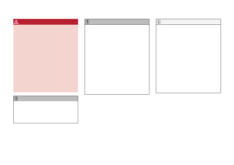
Washer fluid - filling
Washer fluid is used for cleaning the headlamps
and windows. Washer fluid with antifreeze must
be used when the temperature is below freezing
point.
Topping up the washer fluid takes place by open-
ing the blue cap.
The windscreen and headlamp washers share a
common reservoir.
When there is approx. 1 litre of washer fluid
remaining in the reservoir, a message to top
up the washer fluid will be shown in the com-
bined instrument panel, together with the
symbol
.
||
MAINTENANCE AND SERVICE
370
Prescribed grade: Washer fluid recommended
by Volvo - with frost protection during cold
weather and below freezing point.
Use Volvo genuine washer fluid or equivalent
with a recommended pH of between 6 and 8,
in working dilution (e.g. 1:1 with neutral
water).
Use washer fluid with antifreeze when the
temperature is below freezing to avoid freez-
ing in the pump, reservoir and hoses.
Volume:
•
Cars with headlamp washing: 5.4 litres.
•
Cars without headlamp washing: 4.0 litres.
Related information
•
•
•
Bonnet - opening and closing (p. 351)
Starter battery - general
The starter battery is used to drive the starter
motor and other electrical equipment in the car.
The starter battery is a traditional 12 V battery.
The service life and function of the starter battery
is influenced by factors such as the number of
starts, discharging, driving style, driving condi-
tions, climatic conditions, etc.
•
Never disconnect the battery when the
engine is running.
•
Check that the cables to the battery are cor-
rectly connected and properly tightened.
Voltage (V)
12
Cold start capacity
A
- CCA
B
(A)
720
Size, L×W×H (mm)
278×175×190
Capacity (Ah)
70
A
In accordance with EN standard.
B
Cold Cranking Amperes.
When replacing the starter battery in cars
with the Start/Stop function, a battery of
EFB
9
type must be fitted.
When replacing the support battery, a battery
of AGM
10
type must be fitted.
If the starter battery is replaced, make sure
you replace it with a battery with the same
cold starting capacity and type as the original
battery (see the label on the battery).
The starter battery's container size should be
consistent with the original battery's dimen-
sions.
9
Enhanced Flooded Battery.
10
Absorbed Glass Mat.
MAINTENANCE AND SERVICE
371
WARNING
•
The battery can generate oxyhydrogen
gas, which is highly explosive. A spark can
be formed if a jump lead is connected
incorrectly, and this can be enough for
the battery to explode.
•
Do not connect the jump leads to any
fuel system component or any moving
part. Be careful of hot engine parts.
•
The battery contains sulphuric acid, which
can cause serious burns.
•
If sulphuric acid comes into contact with
eyes, skin or clothing, flush with large
quantities of water. If acid splashes into
the eyes - seek medical attention imme-
diately.
•
Never smoke near the battery.
When charging the starter battery or the sup-
port battery (p. 374), only use a modern bat-
tery charger with controlled charging voltage.
Fast charging function must not be used
since it may damage the battery.
If the following instruction is not observed
then the energy saving function for infotain-
ment system may be temporarily disengaged,
and/or the message in the combined instru-
ment panel's information display about the
starter battery's state of charge may be tem-
porarily inapplicable, following the connection
of an external starter battery or battery
charger:
•
The negative battery terminal on the car's
starter battery must never be used for
connecting an external starter battery or
battery charger - only the car chassis
may be used as the grounding point.
See Jump starting with another battery
(p. 275) for a description of how the cable
clamps must be attached.
The life of the battery is shortened if it
becomes discharged repeatedly.
The life of the battery is affected by several
factors, including driving conditions and cli-
mate. Battery starting capacity decreases
gradually with time and therefore needs to be
recharged if the car is not used for a longer
time or when it is only driven short distances.
Extreme cold further limits starting capacity.
To maintain the battery in good condition, at
least 15 minutes of driving/week is recom-
mended or that the battery is connected to a
battery charger with automatic trickle charg-
ing.
A battery that is kept fully charged has a
maximum service life.
Related information
•
•
MAINTENANCE AND SERVICE
372
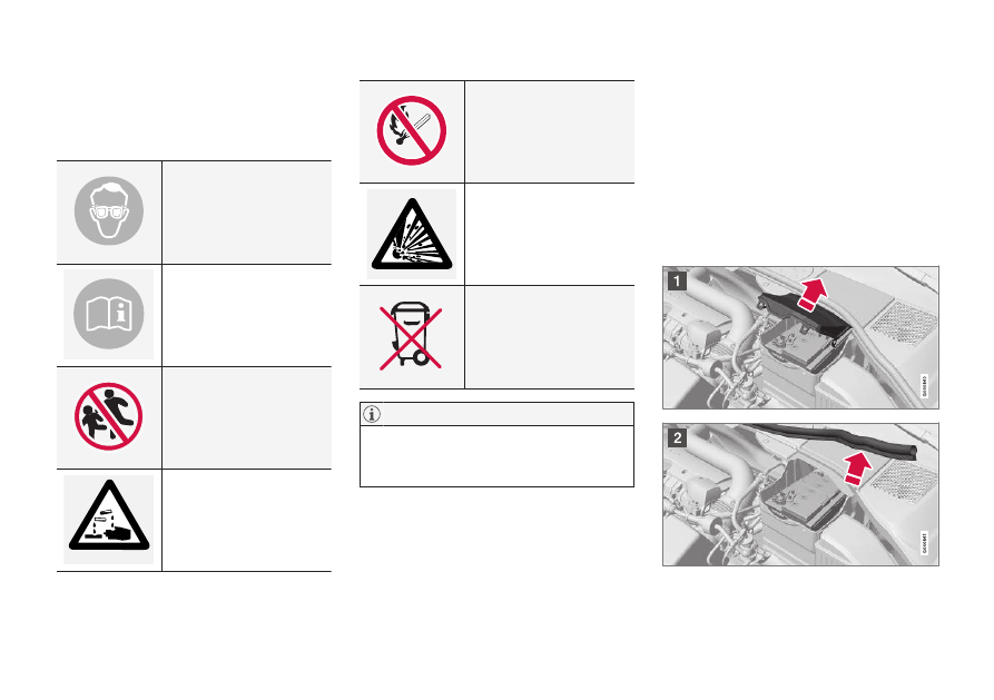
Battery - symbols
There are information and warning symbols on
the batteries.
Symbols on the batteries
Use protective goggles.
Further information in the
owner's manual for the car.
Store the battery out of the
reach of children.
The battery contains corro-
sive acid.
Avoid sparks and naked
flames.
Risk of explosion.
Must be taken for recycling.
An expended starter battery or support bat-
tery must be recycled in an environmentally
safe manner since it contains lead.
Related information
•
Starter battery - general (p. 370)
•
Starter battery - replacement
The starter battery in the car can be replaced
without the help of a workshop.
Removal
First of all: Take the remote control key from the
ignition switch and wait at least 5 minutes before
any electrical connections are touched - this is
because the car's electrical system needs to
store the necessary information to control mod-
ules.
MAINTENANCE AND SERVICE
}}
* Option/accessory.
373
Open the clips on the front cover and remove
the cover.
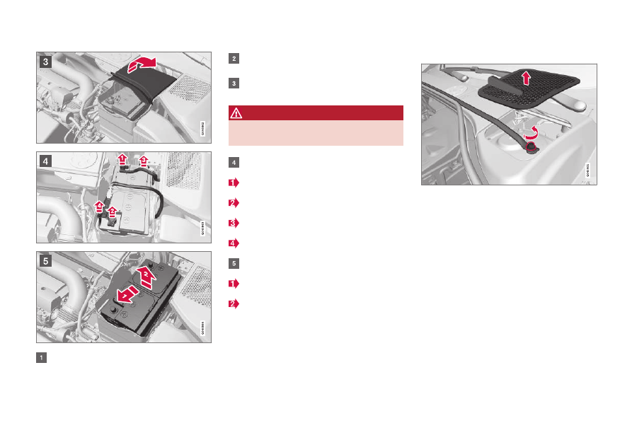
Release the rubber moulding so that the rear
cover is free.
Remove the rear cover by screwing one
quarter turn and lifting it away.
WARNING
Connect and remove the positive and nega-
tive cables in the correct order.
Detach the black negative cable.
Detach the red positive cable.
Detach the ventilation hose from the battery.
Loosen the screw holding the battery clamp.
Move the battery aside.
Lift it up.
Cross-stay on the R-Design
*
Cross-stay and plenum chamber cover.
Cars with R-Design have a cross-stay that must
be removed before the starter battery can be
replaced.
1. Remove the plenum chamber covers on the
right and left-hand sides. Prize carefully with
a plastic knife or similar.
2. Loosen and remove the screws (one on the
right and one on the left-hand side) that hold
the cross-stay.
3. Remove the cross-stay.
> Now the starter battery can be removed in
accordance with the previous section.
•
Fitting the cross-stay takes place in the
reverse order.
||
MAINTENANCE AND SERVICE
* Option/accessory.
374
Tighten the screws to 30 Nm. Check the tor-
que with a torque wrench.
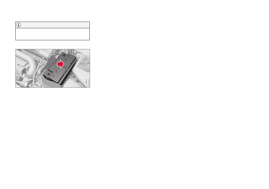
Fitting
1. Lower the battery into the battery box.
2. Move the battery inward and to the side until
it reaches the rear edge of the box.
3. Tighten the clamp that holds the battery.
4. Connect the ventilation hose.
> Check that it is correctly connected to
both battery and outlet in the body.
5. Connect the red positive cable.
6. Connect the black negative cable.
7. Press in the rear cover. (See earlier section
"Removal".)
8. Fit the rubber moulding. (See "Removal".)
9. Align the front cover and secure it with the
clips. (See "Removal".)
For more information on the car's starter battery,
see Starter battery - general (p. 370) and Jump
starting with another battery (p. 275).
Battery - Start/Stop
Cars with the Start/Stop function are equipped
with a support battery in addition to the starter
battery.
Cars with the Start/Stop function are equipped
with two 12 V batteries - one extra powerful bat-
tery for starting and one support battery that
helps during the Start/Stop function's starting
sequence.
For more information on the Start/Stop function,
see Start/Stop
For more information on the car's starter battery,
see Jump starting with another battery (p. 275).
The following table shows specifications for the
starter battery and support battery respectively in
cars with Start/Stop function.
MAINTENANCE AND SERVICE
}}
375
Battery
Start, 12 V
Support, 12 V
Cold
start
capacity
A
- CCA
B
(A)
720
C
760
D
Left-hand drive
car:
120
E
170
F
Right-hand drive
car:
120
Size,
L×W×H
(mm)
278×175×190
Left-hand drive
car:
150×90×106
E
150×90×130
F
Right-hand drive
car:
150×90×106
Battery
Start, 12 V
Support, 12 V
Capacity
(Ah)
70
Left-hand drive
car:
8
E
10
F
Right-hand drive
car:
8
A
In accordance with EN standard.
B
Cold Cranking Amperes.
C
Manual gearbox.
D
Automatic gearbox.
E
Manual gearbox in combination with Start/Stop function that
only auto-stops when the car is completely stationary.
F
Others.
When replacing the starter battery in cars
with the Start/Stop function, a battery of
EFB
11
type or stronger must be installed.
When replacing the support battery, a battery
of AGM
12
type must be fitted.
•
The higher the current take-off in the car,
the more the alternator must be working
and the batteries charging = Increased
fuel consumption.
•
When the capacity of the starter battery
has fallen below the lowest permissible
level then the Start/Stop function is dis-
engaged.
Temporarily reduced Start/Stop function due to
high current take-off means:
•
The engine starts automatically
13
without the
driver depressing the clutch pedal (manual
gearbox).
•
The engine starts automatically without the
driver lifting his/her foot off the foot brake
pedal (automatic gearbox).
11
Enhanced Flooded Battery.
12
Absorbed Glass Mat.
13
Automatic starting can only take place if the gear lever is in neutral position.
Нет комментариевНе стесняйтесь поделиться с нами вашим ценным мнением.
Текст